Sony BKM-FW31 Operating Instructions - Page 21
connector inside the display is firmly, Check the direction top/bottom
 |
View all Sony BKM-FW31 manuals
Add to My Manuals
Save this manual to your list of manuals |
Page 21 highlights
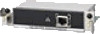
FWD-50PX1N: Loosen the two screws located on the top and bottom of the panel cover. Use a Philips screwdriver to turn the screws counterclockwise, and then remove the panel cover. When the option slot is located on the right side* 2 Check the direction (top/bottom) of this device and insert it into the flat panel display. Make sure that the connector inside the display is firmly connected. Using a slot screwdriver, tighten the two screws of this device. Connect the LAN cable, as needed. CONTROL S IN OUT CONTROL S IN OUT REMOTE REMOTE 1 2 NETWORK MANAGEMENT 2 1 * The location of the option slot differs depending on the model of the Display Unit. Refer to the Instruction Manual of the FWD series as well. 1 2 Caution Do not touch the connectors in the Display. Doing so may result in injury to yourself or cause this device to malfunction. Preparations for Using the Networking Function 7GB
-
 1
1 -
2
-
3
-
4
-
5
-
6
-
7
-
8
-
9
-
10
-
11
-
12
-
13
-
14
-
15
-
 16
16 -
 17
17 -
 18
18 -
 19
19 -
 20
20 -
 21
21 -
 22
22 -
 23
23 -
 24
24 -
 25
25 -
 26
26 -
27
-
28
-
29
-
30
-
31
-
32
-
33
-
34
-
35
-
36
-
37
-
38
-
39
-
40
-
41
-
42
-
43
-
44
-
45
-
46
-
47
-
48
-
49
-
50
-
51
-
52
-
53
-
54
-
55
-
56
-
57
-
58
-
59
-
60
-
61
-
62
-
63
-
64
-
65
-
66
-
67
-
68
-
69
-
70
-
71
-
72
-
73
-
74
-
75
-
76
-
77
-
78
-
79
-
80
-
81
-
82
-
83
-
84
-
85
-
86
-
87
-
88
-
89
-
90
-
91
-
92
-
93
-
94
-
95
-
96
-
97
-
98
-
99
-
100
 |
 |
