Sony BKM-FW32 Operating Instructions - Page 21
Caution, this device and insert it into the flat
 |
View all Sony BKM-FW32 manuals
Add to My Manuals
Save this manual to your list of manuals |
Page 21 highlights
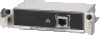
When the option slot is located on the left side of a Display unit* 2 Check the direction (top/bottom) of this device and insert it into the flat panel display. Make sure that the connector inside the Display is firmly connected. Using a slot screwdriver, tighten the two screws of this device. Connect the LAN cable, as needed. AUDIO RGB / COMPONENT INPUT 2 L AUDIO OUT R * The location of the option slot differs depending on the model of the Display unit. If your Display unit has more than one option slot, install the device in a COM port, a slot used for the network. Refer to the Operating Instructions for the FWD series as well. 2 1 2 NETWORK MANAGEMENT Caution Do not touch the connector inside the Display. Doing so may result in injury to yourself or cause this device to malfunction. Preparations for Using the Networking Function 7GB
-
 1
1 -
2
-
3
-
4
-
5
-
6
-
7
-
8
-
9
-
10
-
11
-
12
-
13
-
14
-
15
-
 16
16 -
 17
17 -
 18
18 -
 19
19 -
 20
20 -
 21
21 -
 22
22 -
 23
23 -
 24
24 -
 25
25 -
 26
26 -
27
-
28
-
29
-
30
-
31
-
32
-
33
-
34
-
35
-
36
-
37
-
38
-
39
-
40
-
41
-
42
-
43
-
44
-
45
-
46
-
47
-
48
-
49
-
50
-
51
-
52
-
53
-
54
-
55
-
56
-
57
-
58
-
59
-
60
-
61
-
62
-
63
-
64
-
65
-
66
-
67
-
68
-
69
-
70
-
71
-
72
-
73
-
74
-
75
-
76
-
77
-
78
-
79
-
80
-
81
-
82
-
83
-
84
-
85
-
86
-
87
-
88
-
89
-
90
-
91
-
92
-
93
-
94
-
95
-
96
-
97
-
98
-
99
-
100
 |
 |
