Sony CDP-302 Operating Instructions - Page 9
Connection, Diagram
 |
View all Sony CDP-302 manuals
Add to My Manuals
Save this manual to your list of manuals |
Page 9 highlights
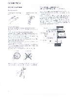
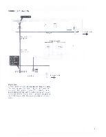
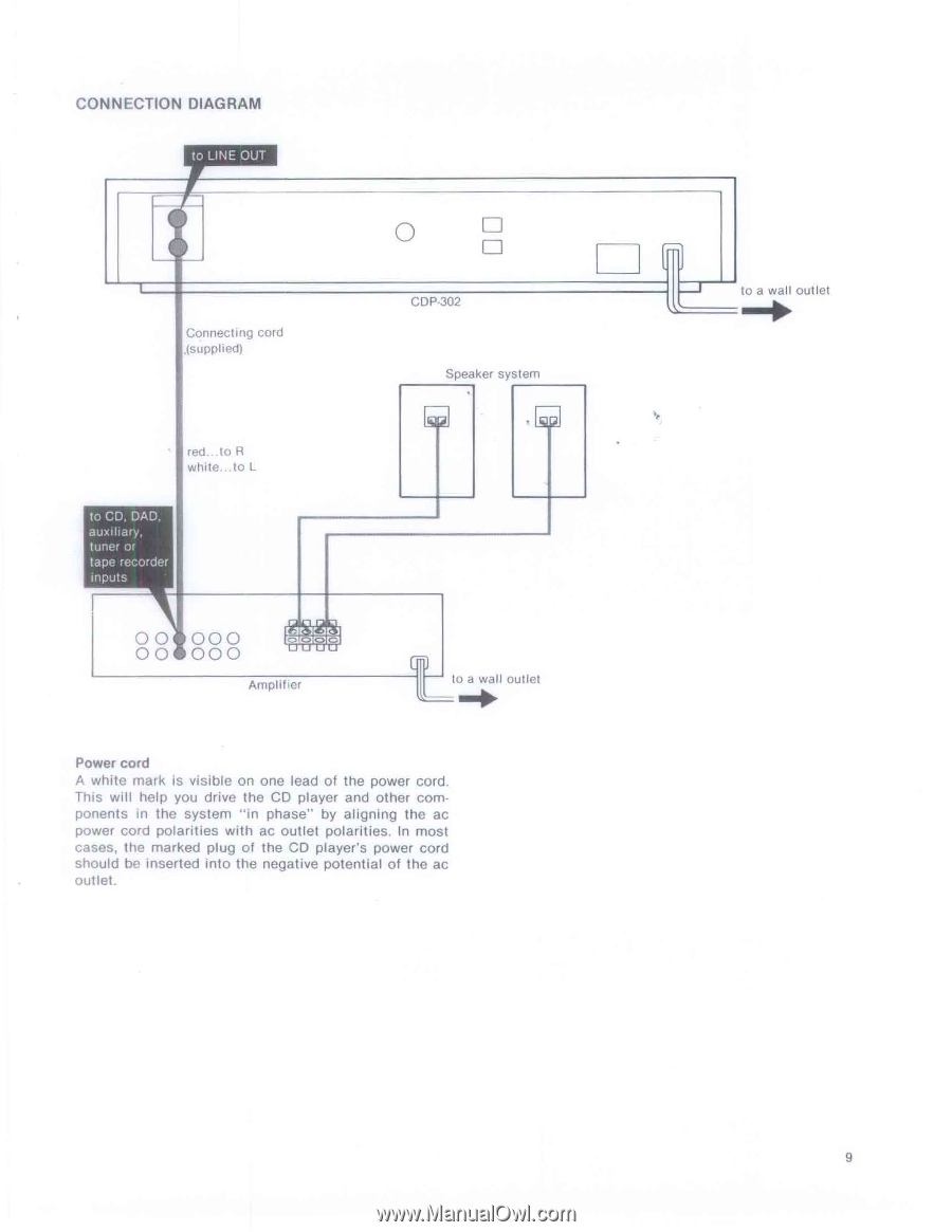
CONNECTION DIAGRAM to LINE OUT Connecting cord .(supplied) 0 CDP-302 Speaker system red...to R white... to L to CD, DAD. auxiliary, tuner or ape recorder inputs 00 00 000 0 0 000 Amplifier to a wall outlet Power cord A white mark is visible on one lead of the power cord. This will help you drive the CD player and other components in the system "in phase" by aligning the ac power cord polarities with ac outlet polarities. In most cases, the marked plug of the CD player's power cord should he inserted into the negative potential of the ac outlet. to a wall outlet 9
-
 1
1 -
2
-
3
-
 4
4 -
 5
5 -
 6
6 -
 7
7 -
 8
8 -
 9
9 -
 10
10 -
 11
11 -
 12
12 -
 13
13 -
 14
14 -
15
-
16
-
17
-
18
-
19
 |
 |
CONNECTION
DIAGRAM
to
LINE
OUT
0
to
a
wall
outlet
CDP-302
Connecting
cord
.(supplied)
Speaker
system
red...to
R
white...
to
L
to
CD,
DAD.
auxiliary,
tuner
or
ape
recorder
inputs
00
00
000
000
0
0
Amplifier
Power
cord
A
white
mark
is
visible
on
one
lead
of
the
power
cord.
This
will
help
you
drive
the
CD
player
and
other
com-
ponents
in
the
system
"in
phase"
by
aligning
the
ac
power
cord
polarities
with
ac
outlet
polarities.
In
most
cases,
the
marked
plug
of
the
CD
player's
power
cord
should
he
inserted
into
the
negative
potential
of
the
ac
outlet.
to
a
wall
outlet
9