Sony CDP-C515 Operating Instructions - Page 5
Connections
 |
View all Sony CDP-C515 manuals
Add to My Manuals
Save this manual to your list of manuals |
Page 5 highlights
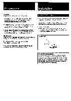
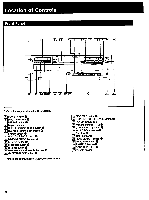
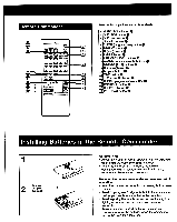
Connections For Correct Connections • Turn off the power of each unit before making connections. • Connect the AC power cord last • Be sure to insert the plugs firmly into the jacks. Loose connection may cause hum and noise. To Connect to an Amplifier • Leave a little slack in the connecting cord to allow for inadvertent shock or vibration. • Cord plugs and jacks are color coded: Red plugs and jacks are for the right channel (R) and white ones for the left channel (L). CDP-0515 / Speaker system r Optical Digital Out When connecting to an amplifier or D/A converter with OPTICAL IN, use OPTICAL DIGITAL OUT instead of LINE OUT. Take off the cap /.041 Plug in firmly O• LINE OUT TitAC outlet SPEAKER • Amplifier ♦ To wall outlet *Notes on LINE OUT • Normally connect the cable to FIXED. (The output level is fixed.) Control the volume with the amplifier's volume control. • When you connect the unit to a power amplifier, connect the cable to VARIABLE and control the volume with the LINE OUT/PHONE LEVEL control or LINE OUT LEVEL buttons on the remote commander. However, if the LINE OUT/PHONE LEVEL control is turned while recording, the recording level will change even when it is preset on the tape deck. Note on optical digital out Connect the optical out to the amplifier with the optical input or D/A converter. When you connect, use the connecting cable for optical out POC-15 (optional). When the optical out is connected, you cannot use fade out, fade in and time fade function. 5
-
 1
1 -
 2
2 -
 3
3 -
 4
4 -
 5
5 -
 6
6 -
 7
7 -
 8
8 -
 9
9 -
 10
10 -
 11
11 -
12
-
13
-
14
-
15
-
16
-
17
-
18
-
19
-
20
 |
 |
