Sony CDP-CX225 Operating Instructions - Page 5
Hookups, Connecting the AC power cord, Note on placement - cd player
 |
View all Sony CDP-CX225 manuals
Add to My Manuals
Save this manual to your list of manuals |
Page 5 highlights
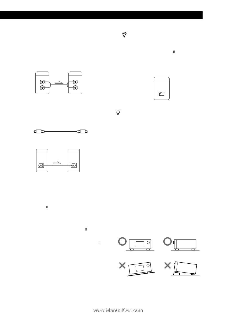
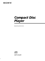
GettPinlagyiSntgarCteDds Hookups When connecting the audio cord, be sure to match the color-coded cord to the appropriate jacks on the components: Red (right) to Red and White (left) to White. Be sure to make connections firmly to avoid hum and noise. CD player LINE OUT L R Amplifier INPUT CD L R • If you have a digital component such as a digital amplifier, D/A converter, DAT or MD Connect the component via the DIGITAL OUT (OPTICAL) connector using an optical cable (not supplied). Take off the cap and plug in the optical cable. POC-15 Optical cable (not supplied) CD player DIGITAL OUT OPTICAL Digital component DIGITAL INPUT OPTICAL Note When you connect via the DIGITAL OUT (OPTICAL) connector, noise may occur when you play CD software other than music, such as a CD-ROM. • If you have a Sony receiver (amplifier) equipped with the CONTROL A1 jack Be sure to connect the player to the CD IN jacks on the receiver (amplifier). When making this connection, set the COMMAND MODE of the player to CD1 (see the illustration below). If you further connect the player and the receiver (amplifier) via the CONTROL A1 jacks with the monaural (2P) mini-plug cord (not supplied), you can use the Auto Function feature between these components. For details, refer to the supplementary "CONTROL-A1 Control System" instructions and the instructions supplied with the receiver (amplifier). When to use the COMMAND MODE selector The COMMAND MODE selector is set to CD1 at the factory for normal use. You can control this player by connecting to a Sony CD Player with the player control function, via the CONTROL A1 jacks. When making this connection, set the COMMAND MODE selectors of each player to the appropriate position according to the connected line input jacks. For details, refer to the instructions supplied with the connected player. COMMAND MODE CD 123 When using another Sony CD player together with this player You can make the supplied remote effective only for this player. • When using the player equipped with the COMMAND MODE selector: Set the COMMAND MODE selector of this player to CD1 and that of another player to CD2 or CD3. Then set the CD1/2/3 switch on the remote supplied for each player accordingly. • When using the player not equipped with the COMMAND MODE selector: The command mode of the player without the COMMAND MODE selector is set to CD1. Set the COMMAND MODE selector of this player to CD2, and set the CD1/2/3 switch on the remote to CD2. Connecting the AC power cord Connect the AC power cord to a wall outlet. Note on placement Be sure to place the player on a horizontal place. If the player is slanted, it may cause malfunction or damage the player. 5
-
 1
1 -
 2
2 -
 3
3 -
 4
4 -
 5
5 -
 6
6 -
 7
7 -
 8
8 -
 9
9 -
 10
10 -
 11
11 -
12
-
13
-
14
-
15
-
16
-
17
-
18
-
19
-
20
 |
 |