Sony CDP-CX260 Operating Instructions - Page 5
Hooking Up the System
 |
View all Sony CDP-CX260 manuals
Add to My Manuals
Save this manual to your list of manuals |
Page 5 highlights
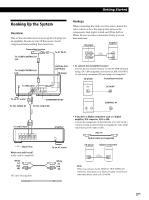
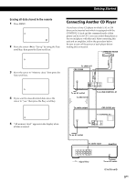
GettPinlagyiSntgarCteDds Hooking Up the System Overview This section describes how to hook up the CD player to an amplifier. Be sure to turn off the power of each component before making the connections. Transmitter/receiver To DC IN 6V To S-LINK/CONTROL A1 jack Hookups When connecting the audio cord, be sure to match the color-coded cords to the appropriate jacks on the components: Red (right) to Red and White (left) to White. Be sure to make connections firmly to avoid hum and noise. CD player 2ND CD LINE IN OUT L L Amplifier INPUT CD L R R R To S-LINK/CONTROL A1 jack To TMR-IA10 DIGITAL OUT (OPTICAL) CD player • To connect the transmitter/receiver Connect the transmitter/receiver via the TO TMR-IA10 jack using a DC-cable (supplied) and via the S-LINK CONTROL A1 jack using a monaural (2P) mini-plug cord (supplied). CD player TO TMR - I A10 ( TRANSMITTER RECEIVER ) DC OUT 6V Transmitter/receiver DC IN 6V To an AC outlet To line output (L) COMMAND MODE To line output (R) S - L I NK CONTROL A1 CONTROL A1 To audio input : Signal flow What cords will I need? Audio cord (1) (supplied) White (L) Red (R) DC-cable (1) (supplied) Amplifier To an AC outlet • If you have a digital component such as a digital amplifier, D/A converter, DAT or MD Connect the component via the DIGITAL OUT (OPTICAL) connector using an optical cable (not supplied). Take off the cap and plug in the optical cable. POC-15 Optical cable (not supplied) CD player DIGITAL OUT OPTICAL Digital component DIGITAL INPUT OPTICAL White (L) Red (R) Note When you connect via the DIGITAL OUT (OPTICAL) connector, noise may occur when you play CD software other than music, such as a CD-ROM. 5EN
-
 1
1 -
 2
2 -
 3
3 -
 4
4 -
 5
5 -
 6
6 -
 7
7 -
 8
8 -
 9
9 -
 10
10 -
 11
11 -
12
-
13
-
14
-
15
-
16
-
17
-
18
-
19
-
20
-
21
-
22
-
23
-
24
-
25
-
26
-
27
-
28
-
29
-
30
-
31
-
32
-
33
-
34
-
35
-
36
-
37
-
38
-
39
-
40
-
41
-
42
-
43
-
44
-
45
-
46
-
47
-
48
-
49
-
50
-
51
-
52
-
53
-
54
-
55
-
56
-
57
-
58
-
59
-
60
-
61
-
62
-
63
-
64
-
65
-
66
-
67
-
68
-
69
-
70
-
71
-
72
-
73
-
74
-
75
-
76
-
77
-
78
-
79
-
80
-
81
-
82
-
83
-
84
-
85
-
86
-
87
-
88
-
89
-
90
-
91
-
92
-
93
-
94
-
95
-
96
-
97
-
98
-
99
-
100
-
101
-
102
-
103
-
104
-
105
-
106
-
107
-
108
-
109
-
110
-
111
-
112
-
113
-
114
-
115
-
116
-
117
-
118
-
119
-
120
 |
 |
