Sony CPD-1303 Operating Instructions (primary manual) - Page 11
Digital, Analog
 |
View all Sony CPD-1303 manuals
Add to My Manuals
Save this manual to your list of manuals |
Page 11 highlights
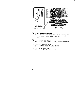
Pin Assignment 543 21 00 0 00 O O 00 9 8 76 12 3 4 56 7 8 9 ANALOG** GND GND R NORMAL GND GND R D1 GND GND R DIGITAL CGA GND GND R D2 MDA GND GND - EGA GND r R G* B GND - H/HV V G B GND -- H/HV V G B I - H/HV V G B I - H/HV V - - I G H/HV V G B g b H/HV V (Input Selection) GND: Ground R: Red Signal G: Green Signal B: Blue Signal -: No connection H: Horizontal Sync V: Vertical Sync NORM 01 D2 DIGITAL HV: Composite sync I: Intensity Signal EMI r: Secondary Red for EGA 64 colors ANALOG g: Secondary Green for EGA 64 colors b: Secondary Blue for EGA 64 colors ANALOG * Sync on Green automatic if horizontal or composite sync is not assigned at Pin #8 - IBM PGA should be connected with PGA Video cable (SMF-513) DIGITAL (TTL LEVEL) "Normal" is for 8 colors (R, G, & B) "Dl" is for 16 colors (R, G, B & I) "D2" is for IBM Digital Color Graphic Boards (CGA, MDA, EGA) anc there is no need to readjust anything among these cards. SYNC Composite sync is acceptable at Pin # 8. Every polarity is acceptable at Pin # 8 & 9. VERTICAL Size Vertical size depends on vertical frequency and can be manually adjusted. 11
-
 1
1 -
2
-
3
-
4
-
5
-
 6
6 -
 7
7 -
 8
8 -
 9
9 -
 10
10 -
 11
11 -
 12
12 -
 13
13 -
 14
14 -
 15
15 -
 16
16 -
17
-
18
-
19
-
20
-
21
-
22
-
23
-
24
-
25
-
26
-
27
-
28
-
29
-
30
-
31
-
32
-
33
-
34
-
35
-
36
-
37
-
38
 |
 |
