Sony CPD-1303 Operating Instructions (primary manual) - Page 8
Connections
 |
View all Sony CPD-1303 manuals
Add to My Manuals
Save this manual to your list of manuals |
Page 8 highlights
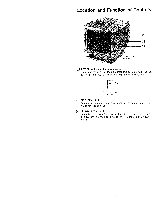
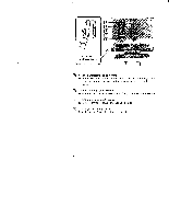
Connections Use an appropriate optional color monitor cable with 9-pin D-sub connectors shown in the table. Be sure to turn the power of the unit off before making any connections. Equipment that can be connected IBM PC, AT, XT with CGA IBM PC, AT, XT with EGA, CGA, MDA IBM 3270 IBM PC, AT, XT with PGA Monitor cable (optional) to be used SMF-512C (SMF-520) SMF-512C (SMF-520) SMF-514 SMF-513 Position of RGB input selectors of the CPD-1303 D1-DIGITAL D2 DIGITAL NORM-DIGITAL ANALOG Rear of the CPD-1303 0 Set to appropriate _ positions. O. OE Microcomputer to RGB OUT (9-pin) to RGB IN 1 optional color monitor cable iii to AC IN to a AC power wall cord (supplied) outlet 1 Align the plug with the receptacle. Plug in and tighten the screws. To disconnect the plug, loosen the screws. 2 8
-
 1
1 -
2
-
 3
3 -
 4
4 -
 5
5 -
 6
6 -
 7
7 -
 8
8 -
 9
9 -
 10
10 -
 11
11 -
 12
12 -
 13
13 -
14
-
15
-
16
-
17
-
18
-
19
-
20
-
21
-
22
-
23
-
24
-
25
-
26
-
27
-
28
-
29
-
30
-
31
-
32
-
33
-
34
-
35
-
36
-
37
-
38
 |
 |
