Sony DCRPC1000 Operating Guide - Page 72
Jacks to connect external devices, Camcorder, Handycam Station
 |
UPC - 027242670051
View all Sony DCRPC1000 manuals
Add to My Manuals
Save this manual to your list of manuals |
Page 72 highlights
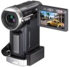
Jacks to connect external devices Camcorder 1 2 3 Handycam Station 8 7 DC IN DV A/V 4 35 6 Active Interface Shoe (p. 67) The Active Interface Shoe supplies power to optional accessories such as a video light, a flash, or a microphone. The accessory can be turned on or off as you operate the POWER switch on your camcorder. Refer to the operating instructions supplied with your accessory for details. • When you connect an accessory, open the shoe cover. Pull up the shoe cover, then rotate it to the direction of the arrow to open. 72 • The Active Interface Shoe has a safety device for fixing the installed accessory securely. To connect an accessory, press down and push it to the end, and then tighten the screw. To remove an accessory, loosen the screw, and then press down and pull out the accessory. • When you are recording on a "Memory Stick Duo" with an external flash (optional) connected to the accessory shoe, turn off the power of the external flash to prevent charging noise being recorded. • You cannot use an external flash (optional) and the built-in flash at the same time. • When an external microphone (optional) is connected, it takes precedence over the internal microphone (p. 27). LANC jack (blue) • The LANC control jack is used for controlling the tape transport of video devices and peripherals connected to it. A/V (audio/video) jack (p. 34, 63, 84) DC IN jack (p. 9) DV Interface (i.LINK) jack (p. 63, 81) (USB) jack • When you set the POWER switch to PLAY/EDIT and connect the USB cable (supplied), the window to check the previous connection setting appears. When you use the connection setting displayed on the screen, touch [OK]. If you touch [SETTING], you can change the connection setting on the [USB SELECT] (p. 52) screen. • When you change the connection setting on the [USB SELECT] screen, the window to check the connection setting won't appear. USB ON/OFF switch Set the USB ON/OFF switch to [ON] while using the USB connection. Interface connector
-
 1
1 -
2
-
3
-
4
-
5
-
6
-
7
-
8
-
9
-
10
-
11
-
12
-
13
-
14
-
15
-
16
-
17
-
18
-
19
-
20
-
21
-
22
-
23
-
24
-
25
-
26
-
27
-
28
-
29
-
30
-
31
-
32
-
33
-
34
-
35
-
36
-
37
-
38
-
39
-
40
-
41
-
42
-
43
-
44
-
45
-
46
-
47
-
48
-
49
-
50
-
51
-
52
-
53
-
54
-
55
-
56
-
57
-
58
-
59
-
60
-
61
-
62
-
63
-
64
-
65
-
66
-
 67
67 -
 68
68 -
 69
69 -
 70
70 -
 71
71 -
 72
72 -
 73
73 -
 74
74 -
 75
75 -
 76
76 -
 77
77 -
78
-
79
-
80
-
81
-
82
-
83
-
84
-
85
-
86
-
87
-
88
-
89
-
90
-
91
-
92
-
93
-
94
-
95
-
96
-
97
-
98
-
99
-
100
-
101
-
102
-
103
-
104
-
105
-
106
-
107
-
108
-
109
-
110
-
111
-
112
-
113
-
114
-
115
-
116
-
117
-
118
-
119
-
120
-
121
-
122
-
123
 |
 |
