Sony DSR 45A Operating Instructions - Page 20
Rear Panel, COUNTER SELECT selector, COUNTER, U-BIT, RESET counter reset button - dsr 45
 |
UPC - 027242689602
View all Sony DSR 45A manuals
Add to My Manuals
Save this manual to your list of manuals |
Page 20 highlights
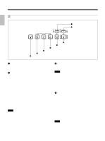
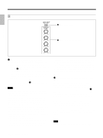
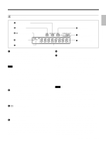
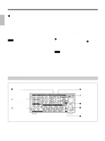
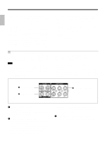
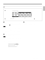
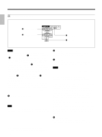
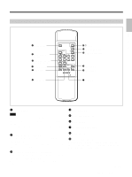
Chapter 1 Overview Location and Function of Parts 7 COUNTER SELECT selector Selects the time data to be indicated on the time counter display. Selected time data is also displayed on the LCD monitor or on the counter display of a monitor connected to the MONITOR VIDEO jack. COUNTER: Count value of the counter (seven digits). The value is displayed on a ±12-hour cycle. TC: Time code U-BIT: User bits Notes • The count value of the counter of this unit is determined by calculation based on the time code, that is, simple approximation. Therefore, in cases such as the following, the value may be inaccurate. - There is a portion where the time code is not continuous on the tape you are using. - The time code in both the drop frame mode and the non-drop frame mode are recorded on the tape you are using (For DSR-45 only). - There is a blank portion between recorded portions on the tape you are using. - A tape recorded using the PAL color system is being used in the DSR-45. - A tape recorded using the NTSC color system is being used in the DSR-45P. - You are using an external time code. - TC RUN on the TC/UB SET menu is set to FREE RUN. • If you intend to edit using an RS-422A connection, set the editing mode of the controller to time code (TC), and set the COUNTER SELECT selector of this unit to TC. 8 RESET (counter reset) button When the COUNTER SELECT selector 7 is set to COUNTER, pressing this button resets the value indicated on the time counter display to 0:00:00:00 (0H00M00S00F). Notes • This button cannot reset the value of the time code or user bits. • To reset the value of the time code or user bits, use TC PRESET or UB PRESET on the TC/UB SET menu. Rear Panel 1 TC connectors 1 Video signal input/ output section (see page 22 (GB)) 2 Audio signal input/ output section (see page 23 (GB)) 5 MONITOR jacks 3 Remote control section (see page 24 (GB)) 4 CONTROL S IN jack 3 AC IN connector 2 DV jack 20 (GB) Chapter 1 Overview
-
 1
1 -
2
-
3
-
4
-
5
-
6
-
7
-
8
-
9
-
10
-
11
-
12
-
13
-
14
-
 15
15 -
 16
16 -
 17
17 -
 18
18 -
 19
19 -
 20
20 -
 21
21 -
 22
22 -
 23
23 -
 24
24 -
 25
25 -
26
-
27
-
28
-
29
-
30
-
31
-
32
-
33
-
34
-
35
-
36
-
37
-
38
-
39
-
40
-
41
-
42
-
43
-
44
-
45
-
46
-
47
-
48
-
49
-
50
-
51
-
52
-
53
-
54
-
55
-
56
-
57
-
58
-
59
-
60
-
61
-
62
-
63
-
64
-
65
-
66
-
67
-
68
-
69
-
70
-
71
-
72
-
73
-
74
-
75
-
76
-
77
-
78
-
79
-
80
-
81
-
82
-
83
-
84
-
85
-
86
-
87
-
88
-
89
-
90
-
91
-
92
-
93
-
94
-
95
-
96
-
97
-
98
-
99
-
100
-
101
-
102
-
103
-
104
-
105
-
106
-
107
-
108
-
109
-
110
-
111
-
112
-
113
-
114
-
115
-
116
-
117
-
118
-
119
-
120
-
121
-
122
-
123
-
124
-
125
-
126
-
127
-
128
-
129
-
130
-
131
-
132
-
133
-
134
-
135
-
136
-
137
-
138
-
139
-
140
-
141
-
142
-
143
-
144
-
145
-
146
-
147
-
148
-
149
-
150
-
151
-
152
-
153
-
154
-
155
-
156
-
157
-
158
-
159
-
160
-
161
-
162
-
163
-
164
-
165
-
166
-
167
-
168
-
169
-
170
-
171
-
172
-
173
-
174
-
175
-
176
-
177
-
178
-
179
-
180
-
181
-
182
-
183
-
184
-
185
-
186
-
187
-
188
-
189
-
190
-
191
-
192
-
193
-
194
-
195
-
196
-
197
-
198
-
199
-
200
-
201
-
202
-
203
-
204
-
205
-
206
-
207
-
208
-
209
-
210
-
211
-
212
-
213
-
214
-
215
-
216
-
217
-
218
-
219
-
220
 |
 |
