II
A
'"
not
supplied
non fourni
no suministrado
1----------------------+-
-------
--
----------------
--
SoNIIIle
rodIo_
(XMISIIlIUS)'
SynIonl
.....
I1ldIo_1Io
(XMISIIllU$)'
_do'-por_1Io
(XIII8!IlIUS)'
Cautions
• This unit is designed for negative ground (earth)
12
V
DC
operation
only.
•
Do
not get the
leads
under
a screw,
or
caught
in moving
parts (e.g. seat railing).
• Before making connections, cum the
car
ignition
off
to
avoid short circuits.
• Connect the
yellow
and
red
power supply leads only
after all
other
leads have been connected.
• Run all ground (earth) leads
to
a common
ground (earth) point.
•
Be
sure to insulate any loose unconnected leads with
electricallape for safety.
• The use
of
optical instruments with this product
will
increase
eye
hazard.
Notes on the power
supply
lead (yellow)
•
When
connecting this unit
in
combination with
other
stereo components, the connected car circuit's rating
must
be
higher than the
sum
of each component's fuse.
• When no car circuits are rated high enough, connect
the unit directly
to
the battery.
Parts
list
[I]
• The numbers in the list are keyed
to
Ihose in the
instructions.
• The bracket
<D
and the protection
collar@
are
~~~a~~~~
~~;h~eU;~:e':~O:;~~it~g~r:::~~:et:o~~~~:t
<D
from the
unit.
For details, see "Removing the
protection collar and the bracket
(EI)"
on the reverse
side
of
the sheet.
•
Keep
the
release
keys
®
for
future
use
as
they
are
also
necessary
if
you
remove
the
unit
from
your
car.
Caution
Handle the bracket
<D
carefully
10
avoid injuring your
fingers.
Note
Before installing,
make
sure
that
the catches
on
both
sides
of
the bracket
<D
are
bent
inwards
2
mm
(3/12
in).
If
the catches
are
straight
or
bent
outwards, the
unit
will
not
be
installed
S8Curely
and
may
spring
out.
Connection
example
[1J
Noteslf)-A)
•
Be
sum
to
conned
the
ground
(earth)
lead
before
connecting
the amplifier.
•
The
alarm
will
only
sound
if
the built-in
amplifier
is
used.
Tips
<f)-B)
•
When connecting
only
a
singlo
CD
changer
or
other
optional
device,
connect
directly to this unit.
•
For
connecting
two
or
more
CD
changers
or
other
optional
devices,
the
soufc8
selector
XA-C40
(not supplied) is
necessary.
*
not
supplied
non fourni
no
suministrado
Notes
on
satellite
radio
tuner
(II-C)
• This unit does not support the
XM
radio tuner
XMD$ONlOO.
•
You
cannot connect two or more satellite radio tuners
(XMlSIRIUS)
to
the XA-C40 at the same time.
• When
you
use
a satellite radio tuner,
be
sure
to
connect
to
the INPUT I temtinal of the XA-C40.
Connection
diagram
[l]
o
To a
metal
surface
of
the
car
First
connect
the
black
ground
(earth) lead, then
connect
the
yellow
and
red
power
supply
leads.
8
To
the
power
antenna
(aerial)
control
lead
or
power
supply
lead
of
antenna
(aerial)
booster
Notes
• It
is
not
necessary
to
connect
this
lead
if
there is no
power
antenna
(aerial)
or
antenna
(aerial) booster,
or
with
a
manually-operated
telescopic
antenna
(aerial).
•
When
your
car
has
a
buitt·in
FM/AM
antenna
(aerial) in
the rear/side glass,
see
"Notes
on
the control
and
power
supply
leads."
e
To AMP REMOTE
IN
of
an
optional
power
amplifier
This connection is
only
for amplifiers.
Connecting
any
other
system
may
damage
the unit.
G
To
the
interface
cable
of
a
car
telephone
e
To a
car's
illumination
signal
Be
sure
to
connect
the
black
ground
(earth)
lead
to
a
metal
surface
of
the
car
first.
e
To
the
+12
V
power
terminal
which
is
energized
in
the
accessory
position
of
the
ignition
switch
Notes
•
If
there is
no
accessory
position,
connect
10
the
+12
V
power
(battery)
terminal
which
is
energized
at
all
times.
Be
sure
to
connect
the
black
ground
(earth)
lead
to
a
metal
surface
of
the
car
first.
•
When
your
car
has
a buitt-in
FM/AM
antenna
(aerial) in
the rear/side glass.
see
"Notes
on
the
control
and
power
supply
leads."
G
To
the
+12
V
power
terminal
which
is
energized
at
all
times
Be
sure
to
connect
the
black
ground
(earth)
lead
to
a
metal
surface
of
the
car
first.
Notes
on
the
control
and
power
supply
leads
•
The
power
antenna
(aerial)
control
lead
(blue) supplies
+12
V
DC
when
you
turn on the tuner.
•
When
your
car
has built·in FMlAM antenna (aerial) in
the
rear/side
glass, connecf the power antenna (aerial) control lead (blue)
or
the accessory powersupply lead
(red)
to the power terminal
of
the
existing antenna (aerial) booster. For details, consult your dealer.
•
A
power
antenna
(aerial) without
a
relay
box
cannot
be
used
with this unit
Memory
hold
connection
When the yellow
power
supply
lead
is connected,
power
will
always
be
supplied
to the
memory
circuit
even when the ignition
switch
is
turned
off.
No'-s
on
speaker
confUlCtlon
•
Before
connecting
the speakers, turn the
unit
off.
•
Use
speakers
with
an
impedance
of
4
to
8
ohms,
and
with
adequate
power
handling
capacities
to
avoid
its damage.
• Do
not
connect
the
speaker
terminals to the
car
chassis,
or
connect
the terminals
of
the
right
speakers
with
those
of
the
left speaker.
• Do
not
connect
the
ground
(earth)
lead
of
this
unit
to
the
negative
(-)
terminal
of
the
speaker.
•
Do
not
attempt
to
connect
the
speakers
in parallel.
•
Connect only passive speakers. Connecting active speakers (with
built·in amplifiers) to the
speaker
terminals
may
damage the unit.
•
To
avoid
a
malfunction,
do
not
use
the built-in
speaker
leads
installed in
your
car
if
the
unit
shares
a
common
negative
(-)
lead
for the right
and
left
speakers.
• Do
not
connect
the
unit's
speaker
leads to
each
other.
Note
on
connection
If
speaker
and
amplifier
are
not
connected
correctly,
~FAILURE"
appears
in the display. In this case,
make
sure
the
speaker
and
amplifier
are
connected
correctly.
*
not
supplied
non fourni
no
suministrado
Precautions
• Cet appareil est exclusivement
con~u
pour fonctionner
sur une tension de
12
V CC
avec
masse negative.
• Evitez
de
fixer
des
vis
sur
les
dibles
ou
de
coincer ceux-ci
dans
des
pieces mobiles (par exemple, annature
de
siege).
• Avant d'effectuer
les
raccordements, coupez
Ie
moteur
pour eviler un court-circuit.
• Raccordez
les
cables
d'
alimentation
laune
et
rouge
seulement apres avoir tennine tous les autres
raccordements.
•
Rassemblez
tous
les
cAbles
de
mise
a
la
masse
en
un
point
de
masse
commun.
• Pour des raisons de securite, veillez
a
isoler avec du
ruban isolant tout dl.ble libre non raccorde.
• L'utilisalion d'instruments optiques
avec
ce produit
augmente les risques pour
les
yeux.
Remarques
sur
Ie
cable
d'alimentatlon
Oaune)
• Lorsque cet appareil est raccorde a d'autres elements
stereo. la valeur nontinale
du
circuit de la voiture
raccorde doit etre sup6rieure a la somme des
fusib1es
de chaque element.
• Si aucun circuit de
Ia
voiture n'est assez puissant.
raccordez directement l'appareil a
la
batterie.
liste
des
composants
[I]
• Les numeros de la liste correspondent a ceux des
instructions.
• Le support
CD
et
Ie
tour de protection
@
sont fixes a
l'appareil
en
usine. Avant
Ie
montage de I'appareil,
utilisez
les
des
de deblocage
®
pour detacher
Ie
support
<D
de I'apparei!. Pour plus de details, reportez-
vous a
la
section
«
Retrait
du
tour
de
protection et
du
support
(EI)
»
au
verso.
•
Conservez
les
cl6s
de
d6blocage
®
pour
une
utilisation
ulterleure
car
vous
en
aurez
egalement
besoln
pour
retirer
I'appareil
de
votre
vehicule.
Attention
Manipulez precautionneusement
Ie
support
CD
pour
eviter de vous blesser aux doigts.
Remarque
Avant
/'installation, assurez-vous
que
les
Ioquets des
deux
~tes
du
support
<D
sont
bien
plies
de
2
mm
('/3:1
po)
vers /'interieur.
Si
les
loquets
sont
droits
ou
plilJs vers l'ext6r1eur,
I'appsreil
ne
peut
pas
~tre
fixe
soiidement
et
peut
56
d6tscher.
 1
1 23
23 24
24 25
25 26
26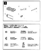 27
27 28
28 29
29 30
30 31
31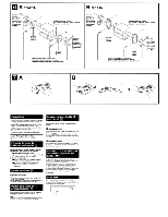 32
32 33
33

