Sony GVM-2000 Operating Instructions - Page 7
Digital/analog
 |
View all Sony GVM-2000 manuals
Add to My Manuals
Save this manual to your list of manuals |
Page 7 highlights
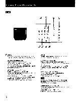
is RGB A interface unit 16, 64 COLOR/8 COLOR selector Depress this selector when digital RGB equipment having 16- or 64-color mode is connected to the RGB A connector. The 16- or 64-color mode is automatically selected by sync polarity. Keep the selector released for digital RGB equipment having the 8-color mode. DIGITAL/ANALOG selector Depress this selector when video equipment having digital RGB output is connected to the RGB A connector. Release the selector for equipment having analog RGB output. RGB A connector (D-sub 9-pin) Connect to video equipment having either digital or analog RGB output. To monitor the input signal fed through this connector, press the RGB A input select button. Note For connection with a microcomputer, be sure to use either of the following optional connecting cables: SMF-521 (9-pin to 15-pin) SMF-522 (9-pin to 9-pin) RGB B interface unit R/G/B connectors (BNC type) Connect to the analog R/G/B outputs of video equipment. To monitor the input signal fed through these connectors, press the RGB B input select button. HVD/HD input connector (BNC type) When video equipment is connected to the R/G/B connectors and does not provide sync signal on G-signal, connect it to the composite sync or horizontal sync output of the equipment. VD input connector (BNC type) Connect to the vertical sync output of video equipment. For video equipment with H/V separate sync signal, connect it to both the HVD/HD and VD connectors. Notes • For video equipment with H/V composite sync and V sync, use only the composite sync connection. • If horizontal sync signal has serration pulses*, the monitored picture may be distorted. Input the horizontal sync signal without serration pulses. *A pulse occurring at periods of twice the horizontal frequency between horizontal-sync pulses SYNC ON GREEN selector When video equipment is connected to the R/G/B connectors; Depress this selector to operate the monitor on the sync signal on G-signal. To operate on the H/V separate sync signal or composite sync signal fed through the HVD/HD and/or VD input connector(s), keep the selector released. Note Be sure to depress the selector (ON) when video equipment providing sync signal on G-signal is connected. Otherwise, color reproduction may not be correct. 16 RGB A SELECT connector (minijack) When ground potential is applied to this connector, signal input from the RGB A connector will be monitored regardless of the setting of the input select buttons on the front panel. If a power supply of 5 V is applied to the connector or the circuit is open, the input signal selected with the input select buttons will be monitored. This connector allows the input source monitored to be selected with external equipment. N CONTROL S input connector (minijack) Connect to the CONTROL S output of video equipment. The power on/off, * pi TCP volume and picture settings can be remotely controlled through the equipment connected. 20 RGB AUTOMATIC WHITE BALANCE switch Normally set this switch to ON. The white balance is adjusted by current feedback circuit. When the vertical picture size of RGB input is reduced with the V SIZE control, a white stripe may appear on the top of the screen. To delete the stripe, set the selector to OFF. The white balance adjustment level in the OFF position is preset at the factory, but there may be some changes in the level over time. RGB A/RGB B AUDIO input jacks (phono type) Connect to the audio outputs of the RGB equipment connected to the RGB A/RGB B connectors. 7
-
 1
1 -
 2
2 -
 3
3 -
 4
4 -
 5
5 -
 6
6 -
 7
7 -
 8
8 -
 9
9 -
 10
10
 |
 |
