Sony GVM-2000 Operating Instructions - Page 9
assignment
 |
View all Sony GVM-2000 manuals
Add to My Manuals
Save this manual to your list of manuals |
Page 9 highlights
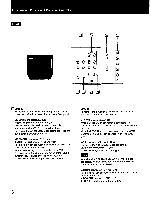
Pin assignment Y/C (Y/C separate) INPUT connector Pin No. 1 Y-input Signal 2 CHROMA sub-carrier-input 3 GND for Y-input 4 GND for CHROMA-input * Slot for internal switch RGB multi connector (9-pin) 1 0 2 0 3 0 4 0 0 0 0 0 0 6 789 Description 1 Vp-p, sync negative, 75 ohms 300 mVp-p, burst Delay time between Y and C: within 0±100 nsec., 75 ohms Ground Ground Press the switch inside this slot. The signal from S-INPUT connector has priority over the one from LINE B VIDEO IN (BNC type) connector. Signal Pin No. 1 2 3 4 5 6 7 8 9 Sync level Analog GND (NC) R G B (NC) (NC) H/HV V HV:1Vp-p (Negative) H,V:TTL level (Positive or Negative) Digital 8-color GND (NC) R G B (NC) (NC) H/HV V TTL level (Positive or Negative) Digital 16-color GND (NC) R G B I (NC) H/HV V TTL level (H:Positive V:Positive) GND: Ground R: Red G: Green B: Blue (NC): No connection H: Horizontal sync V: Vertical sync HV: Composite sync I: Intensity r: Secondary red g: Secondary green b: Secondary blue Design and specifications subject to change without notice. Digital 64-color GND r R G B g b H/HV V TTL level (H:Positive V:Negative) Digital monochrome (GND) (NC) (NC) (NC) (NC) (NC) I H/HV V TTL level (H:Negative V:Negative) 9
-
 1
1 -
2
-
3
-
 4
4 -
 5
5 -
 6
6 -
 7
7 -
 8
8 -
 9
9 -
 10
10
 |
 |
