Sony HCD-HX7 Service Manual - Page 17
Hcd-hx3/hx5/hx7, Electrical, Checks
 |
View all Sony HCD-HX7 manuals
Add to My Manuals
Save this manual to your list of manuals |
Page 17 highlights
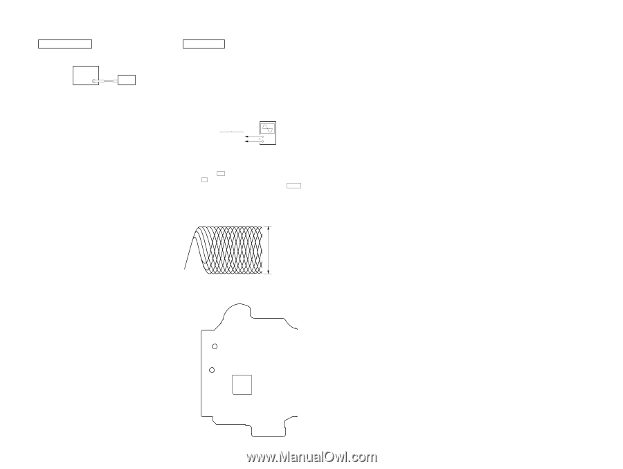
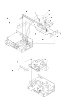
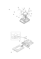
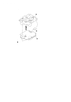
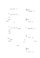
SECTION 5 ELECTRICAL CHECKS TUNER SECTION FM TUNE LEVEL CHECK signal generator set Procedure: 1. Turn on the set. 2. Input the following signal from signal generator to FM antenna input directly. Carrier frequency: A = 87.5 MHz, B = 98 MHz, C = 108 MHz Deviation Modulation ANT input : 75 kHz : 1 kHz : 35 dBu (EMF) Note: Use 75 ohm coaxial cable to connect signal generator and the set. You cannot use video cable for checking. Use signal generator whose output impedance is 75 ohm. 3. Set to FM tuner function and tune A, B and C signals. 4. Confirm "TUNED" is lit on the display for A, B and C signals. When the selected station signal is received in good condition, "TUNED" is displayed. CD SECTION Note: 1. CD Block is basically constructed to operate without adjustment. 2. Use YEDS-18 disc (3-702-101-01) unless otherwise indicated. 3. Use an oscilloscope with more than 10 MΩ impedance. 4. Clean the object lens by an applicator with neutral detergent when the signal level is low than specified value with the following checks. 5. Check the focus bias check when optical pick-up block is replaced. FOCUS BIAS CHECK CD board TP121 (RFI) TP124 (VC) oscilloscope (DC range) + - Procedure : 1. Connect oscilloscope to TP121 (RFI) and TP124 (VC) on the CD board. 2. Press the I/1 button to turn the power on, and press the Z button to open the disc tray. 3. Set disc (YEDS-18) on the tray and press the CD u button to playback. 4. Confirm that oscilloscope waveform is as shown in the figure below. (eye pattern) A good eye pattern means that the diamond shape (◊) in the center of the waveform can be clearly distinguished. VOLT/DIV: 200 mV TIME/DIV: 500 ns level: 0.9 ± 0.4 Vp-p Checking Location: - CD Board (Conductor Side) - TP124 (VC) TP121 (RFI) IC101 HCD-HX3/HX5/HX7 17 17 HCD-HX3/HX5/HX7
-
 1
1 -
2
-
3
-
4
-
5
-
6
-
7
-
8
-
9
-
10
-
11
-
 12
12 -
 13
13 -
 14
14 -
 15
15 -
 16
16 -
 17
17 -
 18
18 -
 19
19 -
 20
20 -
 21
21 -
 22
22 -
23
-
24
-
25
-
26
-
27
-
28
-
29
-
30
-
31
-
32
-
33
-
34
-
35
-
36
-
37
-
38
-
39
-
40
-
41
-
42
-
43
-
44
-
45
-
46
-
47
-
48
-
49
-
50
-
51
-
52
-
53
-
54
-
55
-
56
-
57
-
58
-
59
-
60
-
61
-
62
-
63
-
64
-
65
-
66
-
67
-
68
-
69
-
70
-
71
-
72
-
73
-
74
-
75
-
76
-
77
-
78
-
79
-
80
-
81
-
82
-
83
-
84
-
85
-
86
-
87
-
88
-
89
-
90
 |
 |