Sony HCD-HX7 Service Manual - Page 55
Sony HCD-HX7 - Compact Disc Receiver Manual
 |
View all Sony HCD-HX7 manuals
Add to My Manuals
Save this manual to your list of manuals |
Page 55 highlights
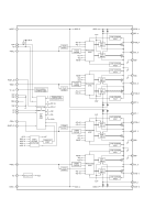
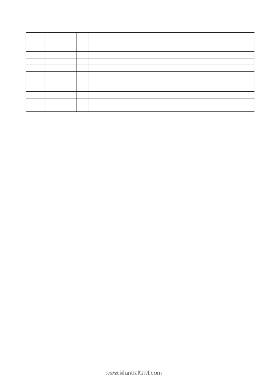
HCD-HX3/HX5/HX7 Pin No. 91 92 93 94 95 96 97 98 99 100 Pin Name LDo MDi RVSS3 FNi2 (C) FNi1 (A) FPi2 (D) FPi1 (B) TPi (F) TNPC TNi (E) I/O Description O Laser diode on/off control signal output to the automatic power control circuit "H": laser diode on I Light amount monitor input from the laser diode of optical pick-up block - Ground terminal I Main beam (C) input from the optical pick-up block I Main beam (A) input from the optical pick-up block I Main beam (D) input from the optical pick-up block I Main beam (B) input from the optical pick-up block I Sub beam (F) input from the optical pick-up block O External capacitor connection terminal I Sub beam (E) input from the optical pick-up block 55
-
 1
1 -
2
-
3
-
4
-
5
-
6
-
7
-
8
-
9
-
10
-
11
-
12
-
13
-
14
-
15
-
16
-
17
-
18
-
19
-
20
-
21
-
22
-
23
-
24
-
25
-
26
-
27
-
28
-
29
-
30
-
31
-
32
-
33
-
34
-
35
-
36
-
37
-
38
-
39
-
40
-
41
-
42
-
43
-
44
-
45
-
46
-
47
-
48
-
49
-
 50
50 -
 51
51 -
 52
52 -
 53
53 -
 54
54 -
 55
55 -
 56
56 -
 57
57 -
 58
58 -
 59
59 -
 60
60 -
61
-
62
-
63
-
64
-
65
-
66
-
67
-
68
-
69
-
70
-
71
-
72
-
73
-
74
-
75
-
76
-
77
-
78
-
79
-
80
-
81
-
82
-
83
-
84
-
85
-
86
-
87
-
88
-
89
-
90
 |
 |
55
HCD-HX3/HX5/HX7
Pin No.
Pin Name
I/O
Description
91
LDo
O
Laser diode on/off control signal output to the automatic power control circuit
"H": laser diode on
92
MDi
I
Light amount monitor input from the laser diode of optical pick-up block
93
RVSS3
-
Ground terminal
94
FNi2 (C)
I
Main beam (C) input from the optical pick-up block
95
FNi1 (A)
I
Main beam (A) input from the optical pick-up block
96
FPi2 (D)
I
Main beam (D) input from the optical pick-up block
97
FPi1 (B)
I
Main beam (B) input from the optical pick-up block
98
TPi (F)
I
Sub beam (F) input from the optical pick-up block
99
TNPC
O
External capacitor connection terminal
100
TNi (E)
I
Sub beam (E) input from the optical pick-up block