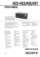
Sony HCD-HX7 Service Manual - Page 3
Table, Contents, Servicing, Notes, General, Disassembly, Electrical, Checks, Diagrams, Exploded, - hcd hx7 40
 |
View all Sony HCD-HX7 manuals
Add to My Manuals
Save this manual to your list of manuals |
Page 3 highlights
HCD-HX3/HX5/HX7 TABLE OF CONTENTS 1. SERVICING NOTES 4 2. GENERAL 5 3. DISASSEMBLY 3-1. Disassembly Flow 9 3-2. Panel (Top 10 3-3. Front Panel Block 10 3-4. MAIN Board (HX3/HX5 11 3-5. MAIN Board/XM Board (HX7 11 3-6. Switching Power Board/Sub Power Board 12 3-7. Loading Mechanism Block 12 3-8. Base Unit 13 3-9. BELT 13 3-10. OP Base Assy (KSM-213D 14 4. TEST MODE 15 5. ELECTRICAL CHECKS 17 6. DIAGRAMS 6-1. Block Diagram - CD SERVO Section 18 6-2. Block Diagram - TUNER/USB/BLUETOOTH Section 19 6-3. Block Diagram - MAIN Section 20 6-4. Block Diagram - AMP Section 21 6-5. Block Diagram - PANEL/POWER SUPPLY Section 22 6-6. Printed Wiring Boards - CD Section 24 6-7. Schematic Diagram - CD Section 25 6-8. Printed Wiring Boards - USB Section (HX3/HX5) - ..... 26 6-9. Schematic Diagram - USB Section (HX3/HX5 27 6-10. Printed Wiring Boards - BLUETOOTH Section (HX5/HX7 28 6-11. Schematic Diagram - BLUETOOTH Section (HX5/HX7 29 6-12. Printed Wiring Boards - XM Section (HX7 30 6-13. Schematic Diagram - XM Section (HX7 31 6-14. Printed Wiring Board - MAIN Section 32 6-15. Schematic Diagram - MAIN Section (1/3 33 6-16. Schematic Diagram - MAIN Section (2/3 34 6-17. Schematic Diagram - MAIN Section (3/3 35 6-18. Printed Wiring Board - AMP Section (HX3/HX7) - ...... 36 6-19. Schematic Diagram - AMP Section (HX3/HX7 37 6-20. Printed Wiring Board - AMP Section (HX5 38 6-21. Schematic Diagram - AMP Section (HX5 39 6-22. Printed Wiring Boards - OUTPUT Section 40 6-23. Schematic Diagram - OUTPUT Section 40 6-24. Printed Wiring Boards - PANEL Section 42 6-25. Schematic Diagram - PANEL Section 43 6-26. Printed Wiring Boards - POWER SUPPLY Section - .... 44 6-27. Schematic Diagram - POWER SUPPLY Section - ........ 45 7. EXPLODED VIEWS 7-1. Panel Section 64 7-2. Chassis (Top) Section 65 7-3. Panel Key Section 66 7-4. Front Panel Section 67 7-5. MAIN Section 68 7-6. Chassis Section 69 7-7. Loading Mechanism Section 70 7-8. Base Unit Section (BU-K6BD90-WOD: HX7) (BU-K6BD90U-WOD: HX3/HX5 71 8. ELECTRICAL PARTS LIST 72 3
-
 1
1 -
 2
2 -
 3
3 -
 4
4 -
 5
5 -
 6
6 -
 7
7 -
 8
8 -
 9
9 -
10
-
11
-
12
-
13
-
14
-
15
-
16
-
17
-
18
-
19
-
20
-
21
-
22
-
23
-
24
-
25
-
26
-
27
-
28
-
29
-
30
-
31
-
32
-
33
-
34
-
35
-
36
-
37
-
38
-
39
-
40
-
41
-
42
-
43
-
44
-
45
-
46
-
47
-
48
-
49
-
50
-
51
-
52
-
53
-
54
-
55
-
56
-
57
-
58
-
59
-
60
-
61
-
62
-
63
-
64
-
65
-
66
-
67
-
68
-
69
-
70
-
71
-
72
-
73
-
74
-
75
-
76
-
77
-
78
-
79
-
80
-
81
-
82
-
83
-
84
-
85
-
86
-
87
-
88
-
89
-
90
 |
 |