Sony HVRM35U Product Manual (HVR-M35U Operating Manuals) - Page 16
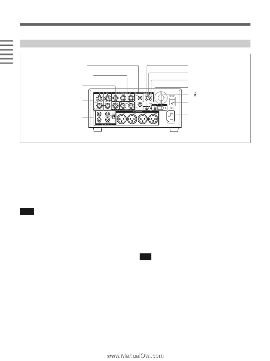
Rear Panel, MONITOR jacks, AES/EBU OUT jacks, TC OUT time code output jack, AC IN connector
 |
View all Sony HVRM35U manuals
Add to My Manuals
Save this manual to your list of manuals |
Page 16 highlights
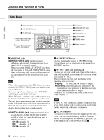
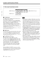
Chapter 1 Overview Location and Function of Parts Rear Panel 1 MONITOR jacks 2 AES/EBU OUT jacks 3 TC OUT jack 1 Video signal input/output section (see page 20) 2 Audio signal input/output section (see page 22) q; LANC jack 9 HD/SD SDI OUT jack 8 RESET button 7 CONTROL S jack 6 HDV/DV jack 5 POWER switch 4 AC IN connector a MONITOR jacks MONITOR VIDEO jack: Outputs standarddefinition video signals. Connect this jack to an input jack of an external monitor. When you set the DISPLAY OUTPUT switch on the front panel to ALL or S VIDEO/VIDEO, data items such as time code, menus or alarm messages are superimposed on the external monitor (page 25). Notes • When video sync signals of the EE pictures are output from the MONITOR VIDEO jack, sync and burst are not synchronized. • The same signals are output from the MONITOR VIDEO jack and VIDEO OUT jack. • When DV input is selected, color and luminance may be distorted in the EE mode, depending on the monitor. • The data items superimposed on a monitor connected to this jack are the same as the items superimposed on the LCD monitor. You cannot make two monitors display different data items simultaneously. MONITOR AUDIO jack: Outputs monaural audio signals. Set the AUDIO MONITOR SELECT switch to select the audio channels you want to monitor as follows. CH-1/2: channels 1/2 MIX: channels 1 to 4 CH-3/4: channels 3/4 b AES/EBU OUT jacks Outputs digital audio signals in AES/EBU format. Connect these jacks to input jacks of devices with an AES/EBU interface. c TC OUT (time code output) jack Outputs the time code of the unit. Connect this jack to a time code input jack on an external device such as a time code reader or a VCR. The unit outputs the time code depending on the operating state as follows: Playing: The time code on the tape is output. Recording: Either the time code generated by the internal time code generator or the time code input from an external device is output. For details, see "HVR-M35U/M35N/M35E/M35P time codes" on page 57. Note If [JOG TC OUT] in the [TC/UB SET] menu has been set to [ON], the time code is output during search mode, but the output time code is not continuous. d AC IN connector Connects to an AC outlet using the supplied power cord. Even if the unit is in the standby mode, it consumes power. To turn the power off completely, press the "a" (OFF) marked side of the POWER switch 5. 16 Chapter 1 Overview
-
 1
1 -
2
-
3
-
4
-
5
-
6
-
7
-
8
-
9
-
10
-
 11
11 -
 12
12 -
 13
13 -
 14
14 -
 15
15 -
 16
16 -
 17
17 -
 18
18 -
 19
19 -
 20
20 -
 21
21 -
22
-
23
-
24
-
25
-
26
-
27
-
28
-
29
-
30
-
31
-
32
-
33
-
34
-
35
-
36
-
37
-
38
-
39
-
40
-
41
-
42
-
43
-
44
-
45
-
46
-
47
-
48
-
49
-
50
-
51
-
52
-
53
-
54
-
55
-
56
-
57
-
58
-
59
-
60
-
61
-
62
-
63
-
64
-
65
-
66
-
67
-
68
-
69
-
70
-
71
-
72
-
73
-
74
-
75
-
76
-
77
-
78
-
79
-
80
-
81
-
82
-
83
-
84
-
85
-
86
-
87
-
88
-
89
-
90
-
91
-
92
-
93
-
94
-
95
-
96
-
97
-
98
-
99
-
100
-
101
-
102
-
103
-
104
-
105
-
106
-
107
-
108
-
109
-
110
-
111
-
112
 |
 |