Sony KZ-32TS1U Operating Instructions - Page 14
Connecting a Digital TV Receiver
 |
View all Sony KZ-32TS1U manuals
Add to My Manuals
Save this manual to your list of manuals |
Page 14 highlights
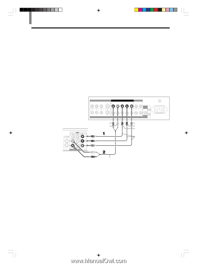
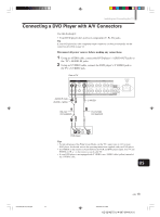
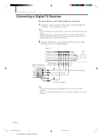
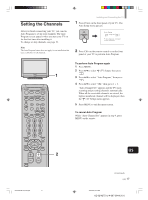
Installing and Connecting the TV Connecting a Digital TV Receiver Disconnect all power sources before making any connections. 1 Using three separate component video cables, connect the Digital TV Set-top box's Y, PB and PR jacks to the TV. Notes • The Y, PB and PR jacks do not provide audio, so audio cables must be connected to provide sound. • Component video (Y, PB, PR) connection is necessary to view 480i, 720p, and 1080i formats. Note that this TV displays all format types of picture in a resolution of 852 dots × 1024 lines (KZ-32TS1), or 1024 × 1024 (KZ-42TS1). 2 Using an AUDIO cable, connect the Digital TV Set-top box's Audio OUT jacks to the TV's AUDIO IN jacks. Rear of TV Digital TV Set-top box VIDEO IN 1 R AUDIO L VIDEO S VIDEO VIDEO IN 2 COMPONENT VIDEO IN 1 AUDIO OUT R AUDIO L Y PB PR R L R AUDIO L Y/G PB/B PR/R HD CONTROL S IN VD OUT COMPONENT VIDEO IN 2 / RGB IN SUB WOOFER AUDIO-R (red) PR AUDIO-L (white) PB Y VHF/UHF AC IN VMC-10HG (not supplied) RK-74A (not supplied) Notes • You cannot record the signal from any equipment connected into the Y, PB and PR connectors. • This TV is not compatible with digital TV receivers configured with RGB or VGA output connectors. 14 (US) 01US04CON-UC(8-19).p65 14 KZ-32/42TS1U 4-087-364-13 (1) 2002.6.22, 3:13 PM
-
 1
1 -
2
-
3
-
4
-
5
-
6
-
7
-
8
-
 9
9 -
 10
10 -
 11
11 -
 12
12 -
 13
13 -
 14
14 -
 15
15 -
 16
16 -
 17
17 -
 18
18 -
 19
19 -
20
-
21
-
22
-
23
-
24
-
25
-
26
-
27
-
28
-
29
-
30
-
31
-
32
-
33
-
34
-
35
-
36
-
37
-
38
-
39
-
40
-
41
-
42
-
43
-
44
-
45
-
46
-
47
-
48
-
49
-
50
-
51
-
52
-
53
-
54
-
55
-
56
-
57
-
58
-
59
-
60
-
61
-
62
-
63
-
64
-
65
-
66
-
67
-
68
-
69
-
70
-
71
-
72
-
73
-
74
-
75
-
76
-
77
-
78
-
79
-
80
-
81
-
82
-
83
-
84
-
85
-
86
-
87
-
88
-
89
-
90
-
91
-
92
-
93
-
94
-
95
-
96
-
97
-
98
-
99
-
100
-
101
-
102
-
103
-
104
-
105
-
106
-
107
-
108
-
109
-
110
-
111
-
112
-
113
-
114
-
115
-
116
-
117
-
118
-
119
-
120
-
121
-
122
-
123
-
124
-
125
-
126
-
127
-
128
-
129
-
130
-
131
-
132
-
133
-
134
-
135
-
136
-
137
-
138
-
139
-
140
-
141
-
142
-
143
-
144
-
145
-
146
-
147
-
148
-
149
-
150
-
151
-
152
-
153
-
154
-
155
-
156
-
157
-
158
-
159
-
160
-
161
-
162
-
163
-
164
-
165
-
166
-
167
-
168
-
169
-
170
-
171
-
172
-
173
-
174
-
175
 |
 |