Sony LF-B20 Operating Instructions - Page 7
Identifying Parts and Controls (LF-B10), Front - locationfree
 |
UPC - 027242702974
View all Sony LF-B20 manuals
Add to My Manuals
Save this manual to your list of manuals |
Page 7 highlights
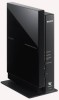
Identifying Parts and Controls (LF-B10) Identifying Parts and Controls (LF-B10) Front NETWORK SETUP MODE/ NET AV SETUP MODE RESET Rear IR BLASTER 1 2 LAN S VIDEO OUT IN OUT VIDEO L AUDIO R DC IN 12V IN 1 VIDEO L AUDIO R IN 2 VIDEO L AUDIO R 1 NETWORK LED Indicates the connection status to a network. Green blinking: Attempting to connect. Green: Connected to the network. The LED blinks quickly when data is transmitted. Off: Not connected. 2 SETUP MODE/NET AV LED Indicates the SETUP MODE status and the connection status with the LocationFree device. Green: Connected to the Base Station. Amber blinking: The Base Station is in Setup mode. Amber: Automatic NetAV check has failed. Off: Not connected. Red: The Base Station is being initialized. 3 SETUP MODE button Press to register LocationFree devices. 4 POWER LED (1 page 11) Green: The power is on. Red: Attempting to be turned off. Red blinking: A malfunction has occurred. Off: The power is off. 5 POWER button (1 page 11) Turns the Base Station power on and off. 6 RESET button (1 page 33) Initializes all settings on the Base Station to the factory defaults. 7 Remote sensor for the learning remote feature (1 page 19) When setting the on-screen remote control or using the learning remote feature, this sensor receives signals from the remote of devices. 8 IR BLASTER 1/2 port (1 page 15) Connect the IR Blaster (supplied). You can purchase another IR Blaster to connect to one of the ports. 9 LAN port (1 page 10) Connect a LAN cable. 0 IN 1 (S-VIDEO/AUDIO/VIDEO) terminal (1 page 14) Connect audio cables and either a video or S-video cable. qa IN 2 (AUDIO/VIDEO) terminal (1 page 14) Connect audio cables and a video cable. qs DC IN jack (1 page 11) Connect the AC power adapter (supplied). qd OUT (S-VIDEO/AUDIO/VIDEO) terminal (1 page 14) Connect audio cables and either a video or S-video cable. The OUT terminal outputs the signals input from the IN 1 terminal. 7
-
 1
1 -
 2
2 -
 3
3 -
 4
4 -
 5
5 -
 6
6 -
 7
7 -
 8
8 -
 9
9 -
 10
10 -
 11
11 -
 12
12 -
13
-
14
-
15
-
16
-
17
-
18
-
19
-
20
-
21
-
22
-
23
-
24
-
25
-
26
-
27
-
28
-
29
-
30
-
31
-
32
-
33
-
34
-
35
-
36
-
37
-
38
-
39
-
40
-
41
-
42
-
43
-
44
-
45
-
46
-
47
-
48
-
49
-
50
-
51
-
52
-
53
-
54
-
55
-
56
-
57
-
58
-
59
-
60
-
61
-
62
-
63
-
64
-
65
-
66
-
67
-
68
-
69
-
70
-
71
-
72
-
73
 |
 |
