Sony PCWA-A500 Operating Instructions - Page 10
Access Point to an Ethernet LAN hub., the Quick Start Guide.
 |
View all Sony PCWA-A500 manuals
Add to My Manuals
Save this manual to your list of manuals |
Page 10 highlights
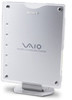
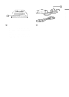
4 NETWORK 1 connector Use an Ethernet cable to connect the Access Point to a DSL modem, cable modem, or ISDN router. 5 NETWORK 2 connector Use an Ethernet cable to connect the Access Point to an Ethernet LAN hub. 6 DC IN 10 V jack Connects to the AC power adapter. Rear view 7 8 9 NETWORK 1 NETWORK 2 DC IN 10V qa NETWORK 1 NETWORK 2 DC IN 10V 0 7 Ferrite core storage recess Insert the ferrite core of the AC adapter cable qd (on page 11) into this recess, then insert the cable into the AC adapter cable securing groove 8 to fix it in place. For details, refer to the Quick Start Guide. 8 AC adapter cable securing groove Insert the ferrite core of the AC adapter cable qd (on page 11) into the ferrite core storage recess 7, then insert the cable into this groove to fix it in place. For details, refer to the Quick Start Guide. 9 Serial number label The serial number (SERIAL NO.) is printed on this label. The numbers printed below "NO." are the serial number. 0 Wall-mounting holes When using the stand/wall-mount adapter as a wall-mount adapter, you can mount the Access Point onto the wall by screwing two screws into the holes. (The screws for mounting the Access Point are not provided. Make sure you use a product that is rated to support the weight of the Access Point.) When mounting the Access Point on a wall, see "Precautions when mounting the Access Point on a wall" (page 24). qa ID label This label is printed with the ID assigned to the Access Point at the time of shipping. (This ID is also referred to as the Network Name (SSID).) This ID is required when configuring Access Point settings. 10
-
 1
1 -
2
-
3
-
4
-
 5
5 -
 6
6 -
 7
7 -
 8
8 -
 9
9 -
 10
10 -
 11
11 -
 12
12 -
 13
13 -
 14
14 -
 15
15 -
16
-
17
-
18
-
19
-
20
-
21
-
22
-
23
-
24
-
25
-
26
-
27
-
28
-
29
-
30
-
31
-
32
 |
 |
