Sony PCWA-A500 Operating Instructions - Page 9
Names of parts and functions - support
 |
View all Sony PCWA-A500 manuals
Add to My Manuals
Save this manual to your list of manuals |
Page 9 highlights
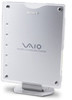
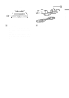
Getting started Names of parts and functions Front view 1 Side view 2 POWER MESSAGE WIRELESS NETWORK 1 NETWORK 2 3 1 Built-in antenna (not externally visible) 2 Indicators POWER Lights green while power is supplied to the Access Point. MESSAGE Lights when unread logs exceed a certain size. The indicator goes out when the log is displayed. WIRELESS Lights green when data can be exchanged on a wireless LAN. Flashes orange while data is being exchanged on a wireless LAN. NETWORK 1 Lights green when an Ethernet cable is connected to the NETWORK 1 connector. Flashes orange while data is being exchanged using the NETWORK 1 connector. 4 5 6 NETWORK 2 Lights green when an Ethernet cable is connected to the NETWORK 2 connector. Flashes orange while data is being exchanged using the NETWORK 2 connector. z Hint All indicators except the POWER indicator flash while the Access Point settings are being changed. 3 Stand/wall-mount adapter The stand/wall-mount adapter is retractable and can be used with the arm extended straight down as a stand or with the arm retracted as a wallmount adapter. When extending the arm straight down, it must not be fixed in a position other than that shown in the illustration above. To get the best performance from the built-in antenna, position the Access Point so that the front of the unit creates a right angle with the supporting surface. 9
-
 1
1 -
2
-
3
-
 4
4 -
 5
5 -
 6
6 -
 7
7 -
 8
8 -
 9
9 -
 10
10 -
 11
11 -
 12
12 -
 13
13 -
 14
14 -
15
-
16
-
17
-
18
-
19
-
20
-
21
-
22
-
23
-
24
-
25
-
26
-
27
-
28
-
29
-
30
-
31
-
32
 |
 |
