Sony SRPX700P Product Manual (SRP-X700P Hardware Operation Manual 1.3) - Page 12
System Configuration, System example when operating the SRP-X700P with the default setting when
 |
View all Sony SRPX700P manuals
Add to My Manuals
Save this manual to your list of manuals |
Page 12 highlights
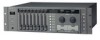
System Configuration System example when operating the SRP-X700P with the default setting when shipped from the factory 12 S VIDEO VIDEO R/G/B/HD/VD Y/R-Y/B-Y RS-232C LCD data projector To power outlet Front speaker (L) Front speaker (R) MD recorder VHS VCR IR transmitter DVD player ANT IN a DC 9V OUT 35mA MAX S VIDEO VIDEO LINE4 INPUT COMPONENT/RGB ANT IN b DC 9V OUT 35mA MAX LINE3 IN L R A B C L L R R FRONT D REAR L R CENTER FRONT E REAR L WOOFER R CENTER WOOFER F L R 1 +48V 2 +48V MIC INPUT 3 +48V 4 +48V MIC5/LINE1 IN (+48V) MIC LINE ON OFF ON OFF ON OFF ON OFF OUTPUT S VIDEO VIDEO R/R-Y G/Y B/B-Y SYNC/HD VD CONTROL S OUTPUT 1 3 PROJECTOR CONTROL CONTROL S IN RS-232C 2 4 OUT CH-2 IMPEDANCE USE 4-16 SPEAKERS CH-1 IMPEDANCE USE 4-16 PARALLEL 70V LINE IMPEDANCE USE 32 -10k REMOTE RS-232C MIC6/LINE2 IN (+48V) MIC LINE LINE OUTPUT REC OUT 3 5 7 1 1 2 4 6 8 2 AC IN CIRCUIT BREAKER PUSH RESET USER CONTROL PANEL USB Surround speaker (LS) Surround speaker (RS) Component 5.1 channel surround To power outlet Power amplifier Center speaker (C) Sub woofer (SW) CD player Power amplifier Ceiling speaker PC 1 RGB AUDIO PC 2 RGB AUDIO Power amplifier • You can realize the above system configuration with the default setting of the SRP-X700P. You can use the system without changing any setups from the supplied software SRP-X700P Manager. • You can control the VHS, DV and DVD, can select channel of the LINE4 INPUT terminal, and can control the sound volume of microphone and AV equipment from the supplied software User Control Panel. (CD and MD cannot be controlled.) • VHS, DV and DVD cannot be controlled from the front panel of the SRP-X700P. • The system configuration shown above uses the two unit of the UHF synthesizer tuner unit WRU-806B (option). • If you want to use an electret condenser microphone for MIC3 and MIC4, set the +48 V button of the corresponding channel to ON. • Connect the VPL-FX51 as a projector through RS-232C. • Install the IR transmitter VM-50 in the SRP-X700P or in the location inside a rack that allows its receptor block to receive the remote control signal. For the installation of the VM-50, see "How to Control AV Equipment from the SRP-X700P" on page 11. • If you use VHS and DV that can select their remote control mode, set the remote control mode of VHS to "VTR3" and set the remote control mode of DV to "VTR4".
-
 1
1 -
2
-
3
-
4
-
5
-
6
-
 7
7 -
 8
8 -
 9
9 -
 10
10 -
 11
11 -
 12
12 -
 13
13 -
 14
14 -
 15
15 -
 16
16 -
 17
17 -
18
-
19
-
20
 |
 |
