Sony SRR1 Product Manual (SRMASTER: SRR1 Operation Manual) - Page 11
Rear and Right Side View, CTRL PANEL Control Panel connector
 |
View all Sony SRR1 manuals
Add to My Manuals
Save this manual to your list of manuals |
Page 11 highlights
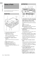
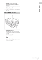
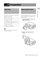
Chapter 1 Overview 8. REMOTE (remote control input) connector (14-pin, female) (for future expansion) 9. DC IN (DC power input) connector (4-pin XLR, male) (page 16) 10. CTRL PANEL (Control Panel) connector (page 16) Rear and Right Side View 1 2 3 1. Power switch (page 22) Setting the switch to the ? side turns power on, and setting the switch to the 1 side turns power off. 2. Cable clamp (page 16) 3. Fan Note Do not block the ventilation openings. Otherwise internal heat buildup can lead to a risk of fire and damage to the unit. Names of Parts 11
-
 1
1 -
2
-
3
-
4
-
5
-
 6
6 -
 7
7 -
 8
8 -
 9
9 -
 10
10 -
 11
11 -
 12
12 -
 13
13 -
 14
14 -
 15
15 -
 16
16 -
17
-
18
-
19
-
20
-
21
-
22
-
23
-
24
-
25
-
26
-
27
-
28
-
29
-
30
-
31
-
32
-
33
-
34
-
35
-
36
-
37
-
38
-
39
-
40
-
41
-
42
-
43
-
44
-
45
-
46
-
47
-
48
-
49
-
50
-
51
-
52
-
53
-
54
-
55
-
56
-
57
-
58
-
59
-
60
-
61
-
62
-
63
 |
 |
Names of Parts
11
Chapter 1
Overview
8.
REMOTE (remote control input)
connector (14-pin, female) (for future
expansion)
9.
DC IN (DC power input) connector (4-pin
XLR, male)
(page 16)
10.
CTRL PANEL (Control Panel) connector
(page 16)
1.
Power switch
(page 22)
Setting the switch to the
?
side turns power
on, and setting the switch to the
1
side turns
power off.
2.
Cable clamp
(page 16)
3.
Fan
Note
Do not block the ventilation openings.
Otherwise internal heat buildup can lead to a risk of
fire and damage to the unit.
Rear and Right Side View
1
3
2