Sony SRR1 Product Manual (SRMASTER: SRR1 Operation Manual) - Page 37
Making Superimpose Settings, To display warning/error messages
 |
View all Sony SRR1 manuals
Add to My Manuals
Save this manual to your list of manuals |
Page 37 highlights
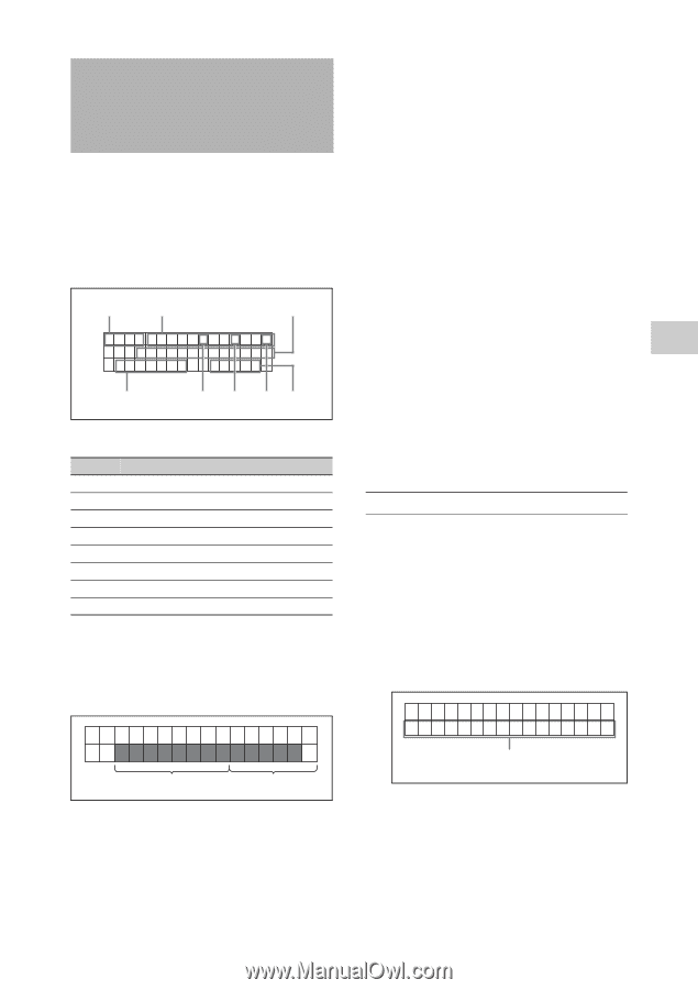
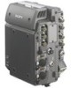
Making Superimpose Settings Time codes, operating modes, warning/error messages, and other text information can be superimposed on (added to) the video signals output from the HD SDI OUT (MON) connectors. Superimposed information displayed 1 Time data 2 TCR . 1 2 : 3 4 . 5 6 . 0 1 * PLAY L OC K R1 2 3m i n 13 . 8V 3 4 5 67 a Time data types Symbol Meaning TM1 Data of TM1 counter TM2 Data of TM2 counter TCR Time code data of LTC reader UBR User bit data of LTC reader TCR. Time code data of VITC reader UBR. User bit data of VITC reader TCG Time code data of time code generator UBG User bit data of time code generator b Operation mode The information is divided into blocks A and B and displayed as shown below. Block A: Operating mode Block B: Mode lock state or playback speed A B There are the following operating mode indications. "SYSTEM READY" "REC" "REC LOCK" "PLAY" "PLAY LOCK" "PLAY PAUSE" "F.FWD" "REW" "UNMOUNT" "STOP" c Remaining amount of recording time on SRMemory card d Drop frame mark of the time code reader " . ": When drop frame mode " : ": When non-drop frame mode e Drop frame mark of the time code generator " . ": When drop frame mode " : ": When non-drop frame mode f VITC field mark " " (blank): When odd field displayed "*": When even field displayed g Battery voltage Indicates the voltage of the battery or AC power supply. To display warning/error messages 1 Set CHAR >MODE in the TC Setup menu to other than "TIME." 2 Set "WARN" to "W+E" to display both warning messages and error messages, and set it to "ERR" to display only error messages. The first 16 characters of a message flash on the second line. TCR . 2 3 : 5 9 : 4 0 : 1 8 NO SD I I NPUT A First 16 characters of a warning/error message For details, see "Error Messages and Warning Messages" (page 52). When there are multiple warning/error messages at the same time, a message flashes twice in succession and then is replaced by the next message. Making Superimpose Settings 37 Chapter 4 Recording and Playback
-
 1
1 -
2
-
3
-
4
-
5
-
6
-
7
-
8
-
9
-
10
-
11
-
12
-
13
-
14
-
15
-
16
-
17
-
18
-
19
-
20
-
21
-
22
-
23
-
24
-
25
-
26
-
27
-
28
-
29
-
30
-
31
-
 32
32 -
 33
33 -
 34
34 -
 35
35 -
 36
36 -
 37
37 -
 38
38 -
 39
39 -
 40
40 -
 41
41 -
 42
42 -
43
-
44
-
45
-
46
-
47
-
48
-
49
-
50
-
51
-
52
-
53
-
54
-
55
-
56
-
57
-
58
-
59
-
60
-
61
-
62
-
63
 |
 |