Sony STR-DA3400ES Operating Instructions (Large File - 15.18 MB) - Page 10
Audio Input/output Video/audio Input/output
 |
View all Sony STR-DA3400ES manuals
Add to My Manuals
Save this manual to your list of manuals |
Page 10 highlights
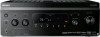
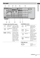
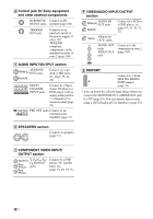
D Control jack for Sony equipment and other external components IR REMOTE Connect an IR IN/OUT jacks repeater (page 104). TRIGGER OUT jack Connects to an interlock on/off of the power supply of other 12V TRIGGER compliant components, or the amplifier/receiver of zone 2 (page 106). E AUDIO INPUT/OUTPUT section AUDIO IN/ White (L) OUT jacks Red (R) Connect to a tape deck or MD deck, etc. (page 19, 21, 24). MULTI CHANNEL INPUT jacks Connect to a Super Audio CD player or DVD player with an analog audio jack for 7.1 channel or 5.1 channel sound (page 23). PRE OUT jacks Connect to an external power amplifier (page 17). F SPEAKERS section Connects to speakers (page 17). H VIDEO/AUDIO INPUT/OUTPUT section AUDIO IN/ White (L) OUT jacks Red (R) Connect to a VCR or a DVD player, etc. (page 19, 29, 30, 31, 32). Yellow VIDEO IN/ OUT* jacks AUDIO OUT jacks VIDEO OUT jack Connects to the component in zone 2 (page 104). I DMPORT Connects to a Sony DIGITAL MEDIA PORT adapter (page 21). * You can watch the selected input image when you connect the MONITOR OUT or HDMI OUT jack to a TV (page 19). You can operate this receiver using a GUI (Graphical User Interface) (page 39). G COMPONENT VIDEO INPUT/ OUTPUT section Green (Y) Y, PB/CB, PR/ Blue (PB/CB) CR IN/OUT* jacks Red (PR/CR) Connect to a DVD player, TV, satellite tuner, etc. (page 19, 29, 30, 31). 10US
-
 1
1 -
2
-
3
-
4
-
 5
5 -
 6
6 -
 7
7 -
 8
8 -
 9
9 -
 10
10 -
 11
11 -
 12
12 -
 13
13 -
 14
14 -
 15
15 -
16
-
17
-
18
-
19
-
20
-
21
-
22
-
23
-
24
-
25
-
26
-
27
-
28
-
29
-
30
-
31
-
32
-
33
-
34
-
35
-
36
-
37
-
38
-
39
-
40
-
41
-
42
-
43
-
44
-
45
-
46
-
47
-
48
-
49
-
50
-
51
-
52
-
53
-
54
-
55
-
56
-
57
-
58
-
59
-
60
-
61
-
62
-
63
-
64
-
65
-
66
-
67
-
68
-
69
-
70
-
71
-
72
-
73
-
74
-
75
-
76
-
77
-
78
-
79
-
80
-
81
-
82
-
83
-
84
-
85
-
86
-
87
-
88
-
89
-
90
-
91
-
92
-
93
-
94
-
95
-
96
-
97
-
98
-
99
-
100
-
101
-
102
-
103
-
104
-
105
-
106
-
107
-
108
-
109
-
110
-
111
-
112
-
113
-
114
-
115
-
116
-
117
-
118
-
119
-
120
-
121
-
122
-
123
-
124
-
125
-
126
-
127
-
128
-
129
-
130
-
131
-
132
-
133
-
134
-
135
-
136
-
137
-
138
-
139
-
140
-
141
-
142
-
143
-
144
 |
 |
