Sony STR-K700 Service Manual - Page 32
Pin No., Pin Name, Description - remote control
 |
View all Sony STR-K700 manuals
Add to My Manuals
Save this manual to your list of manuals |
Page 32 highlights
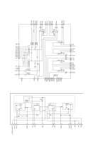
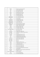
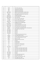
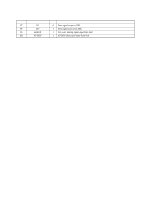
STR-K700 Pin No. 48 49 50 51 52 53 54 55 56 57 58 59 60 61 62 63 64 65 66 67 68 69 70 71 72 73 74 75 76 77 78 79 80 81 82 83 84 85 86 87 88 89 90 91 92 93 94 95 96 32 Pin Name STOP MD0 MD1 MD2 RDS_CLOCK RDS_DATA SIRCS HP_DETECT POWER_KEY ADCC_DSP_IN POWER RY FL_DATA FL_CLK PROTECTOR HP_RY FUSE_DETECT VOL_ENC (A) VOL_ENC (B) FRONT_RY C/SB_RY REAR_RY NOT_USED NOT_USED NOT_USED NOT_USED DO SLATCH TUNED STEREO RSTX MUTE X1A X0A VSS X0 X1 VCC3 NOT_USED SW1 SW2 SW3 SW4 NOT_USED NOT_USED LRCK_SW XMODE CKSEL 1 CLK CE I/O Description I AC off detect signal input I Operation mode setting input I Operation mode setting input I Operation mode setting input I RDS clock signal input (Short to ground terminal) I RDS data signal input (Short to ground terminal) I Data signal input from the remote control sensor I Headphone signal input I Power switch key detect signal input O ADCC DSP input O Power relay control signal output O FL driver signal output terminal O FL driver clock signal output terminal I Protector status detect signal input O Headphone relay control signal output I Fuse detect signal input I Volume signal input from rotary encoder I Volume signal input from rotary encoder O Front speaker relay control signal output O Center speaker or Surround back speaker control signal output O Rear speaker control signal output - Not used - Not used - Not used - Not used I Frequency data signal input from the tuner O Latch signal output to the tuner I Tuning a frequency signal input from the tuner I Stereo tuning signal input from the tuner I System reset input O Muting signal output to the tuner - Not used - Ground terminal - Ground terminal - Connection for a crystal resonator - Connection for a crystal resonator - Power supply (+3.3V) - Not used O Video select control signal output (Not used) O Video select control signal output (Not used) O Video select control signal output (Not used) O Video select control signal output (Not used) - Not used - Not used O LRCK signal output to the selector O Reset signal output to DIR O CKSEL control signal output to DIR O Clock signal output to DIR O Chip enable signal output to DIR
-
 1
1 -
2
-
3
-
4
-
5
-
6
-
7
-
8
-
9
-
10
-
11
-
12
-
13
-
14
-
15
-
16
-
17
-
18
-
19
-
20
-
21
-
22
-
23
-
24
-
25
-
26
-
 27
27 -
 28
28 -
 29
29 -
 30
30 -
 31
31 -
 32
32 -
 33
33 -
 34
34 -
 35
35 -
 36
36 -
 37
37 -
38
-
39
-
40
-
41
-
42
-
43
-
44
-
45
-
46
 |
 |