Sony STR-K7100 Service Manual - Page 50
Ic1907 Mb91353apmt-g-112e1 System Control Digital Board 2/3
 |
View all Sony STR-K7100 manuals
Add to My Manuals
Save this manual to your list of manuals |
Page 50 highlights
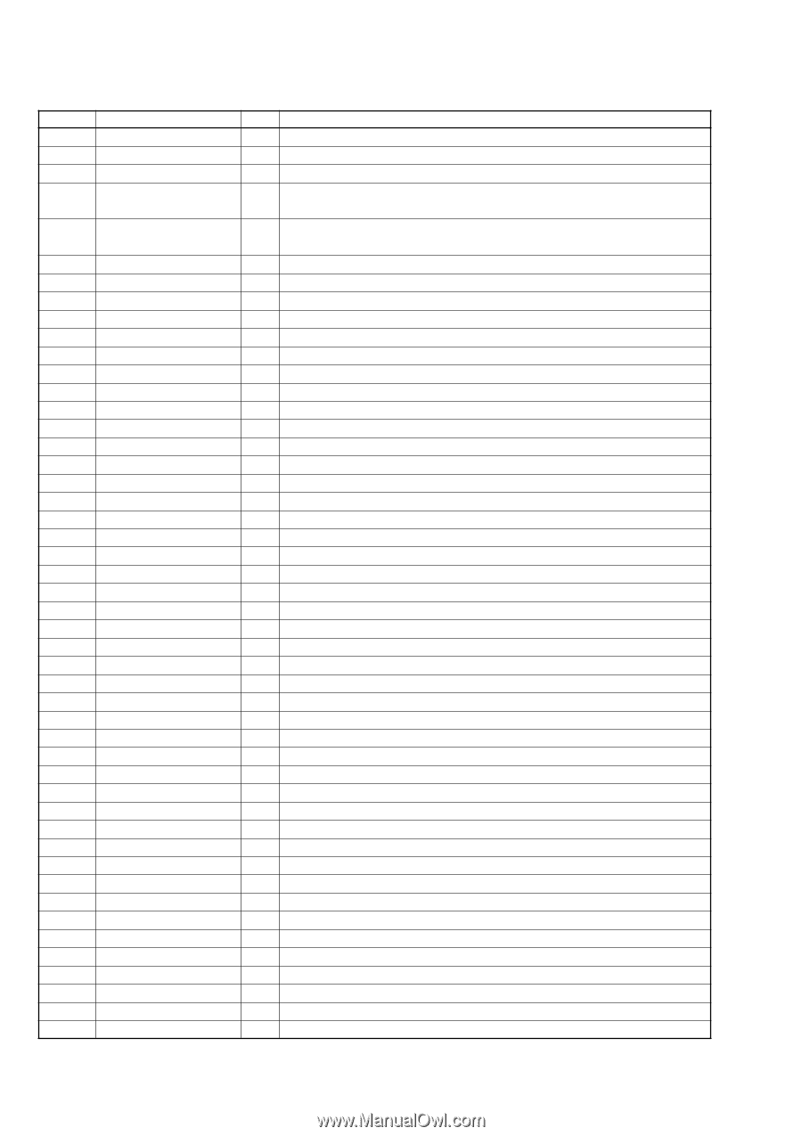
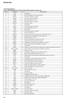
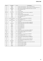
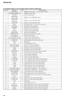
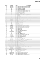
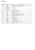
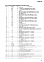
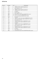
STR-K7100 IC1907 MB91353APMT-G-112E1 (SYSTEM CONTROL) (DIGITAL BOARD (2/3)) Pin No. Pin Name I/O Pin Description 1 HDMI MUTE I HDMI mute signal input Not used in this set. (Open) 2 HDMI RESET/HDMI PRE O HDMI reset signal output 3 XM RESET O XM reset signal output XMDACMDI/ 4 O XM D/A converter MDI signal output PCM1609 MDI XMDACMC/ 5 O XM D/A converter MC signal output PCM1609 MC 6 XMDACMS O XM D/A converter MS signal output 7 SUB T O Sub T signal output Not used in this set. (Open) 8 HP DETECT I Headphone detect signal input 9 POWER RY O Power relay control signal output 10 VOL CL O Volume serial clock signal output 11 VOL DA O Volume serial latch signal output 12 PROTECTOR I Protect control signal input 13 BRIDGEABLE RY O Bridgeable relay control signal output 14 FUSE DETECT I Fuse detect signal input 15 VOL ENCODER(B) UP I Volume encoder signal input (up) 16 VOL ENCODER(A) DOWN I Volume encoder signal input (down) 17 FRONT B RY O Front B speakers relay control signal output 18 GND - Ground pin 19 VCC - Power supply pin (+3.3 V) 20 INPUT ENCODER A I Input select encoder signal input A 21 INPUT ENCODER B I Input select encoder signal input B 22 SW RY O Sub woofer relay control signal output 23 HP RY O Headphone relay control signal output 24 C/REAR/SB RY O Center/surround speaker relay control signal output 25 FRONT RY O Front speaker relay control signal output 26 TUN DO I Tuner serial data signal input 27 TUN LAT O Tuner serial latch signal output 28 V MUTE O Video mute control signal output 29 V COMP SW2 O Video component select switch control signal output 2 30 V COMP SW1 O Video component select switch control signal output 1 31 V SW4 O Video input select switch control signal output 4 32 V SW3 O Video input select switch control signal output 3 33 V SW2 O Video input select switch control signal output 2 34 V SW1 O Video input select switch control signal output 1 35 TUNING ENCODER A I Tuning encoder signal input A Not used in this set. 36 TUNING ENCODER B I Tuning encoder signal input B Not used in this set. 37 PCM1609 RESET O A/D and D/A converters reset signal output 38 DIR XMODE O Digital audio interface receiver reset signal output 39 DIR CLK SEL O Digital audio interface receiver serial clock select signal output 40 VSS - Ground pin 41 TC74HC153A O Input select switch control signal output A 42 TC74HC153B O Input select switch control signal output B 43 VSS - Ground pin 44 VCC - Power supply pin (+3.3 V) 45 DIR CLK O Digital audio interface receiver serial clock signal output 46 DIR CE(LAT) O Digital audio interface receiver serial latch signal output 47 DIR DI O Digital audio interface receiver serial data signal output 48 DIR DO I Digital audio interface receiver serial data signal input 50
-
 1
1 -
2
-
3
-
4
-
5
-
6
-
7
-
8
-
9
-
10
-
11
-
12
-
13
-
14
-
15
-
16
-
17
-
18
-
19
-
20
-
21
-
22
-
23
-
24
-
25
-
26
-
27
-
28
-
29
-
30
-
31
-
32
-
33
-
34
-
35
-
36
-
37
-
38
-
39
-
40
-
41
-
42
-
43
-
44
-
 45
45 -
 46
46 -
 47
47 -
 48
48 -
 49
49 -
 50
50 -
 51
51 -
 52
52 -
 53
53 -
 54
54 -
 55
55 -
56
-
57
-
58
-
59
-
60
-
61
-
62
-
63
-
64
-
65
-
66
-
67
-
68
-
69
-
70
-
71
-
72
-
73
-
74
 |
 |