Sony XR-65X90K Wall-Mount Bracket - Page 14
Align, to the wall and make, four marks., Drill pilot holes on the marks., Install, on the wall.,
 |
View all Sony XR-65X90K manuals
Add to My Manuals
Save this manual to your list of manuals |
Page 14 highlights
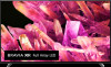
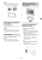
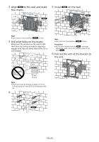
2 Align WM1 to the wall and make four marks. 5 Install WM1 on the wall. × 4 WM1 WM1 Note ˎˎUse a level to check whether WM1 is level. 3 Drill pilot holes on the marks. Make sure the location on the wall to drill the holes are strong enough to support a weight of at least six times that of the TV or LCD Display. × 4 WW1 WS2 Note ˎˎUse a level to check whether WM1 is level. Precaution ˎˎDo not over-tighten lag bolts WS2 . Improper tightening could reduce the holding power of lag bolts WS2 . 6 Pull out the arm of the bracket to the end. 10 mm (13/32 inch) 75 mm (3 inch) Note ˎˎPilot holes must be drilled to a depth of 75 mm (3 inch), using a 10 mm (13/32 inch) diameter drill bit. 4 WA1 − 14 (US) −
-
 1
1 -
2
-
3
-
4
-
5
-
6
-
7
-
8
-
 9
9 -
 10
10 -
 11
11 -
 12
12 -
 13
13 -
 14
14 -
 15
15 -
 16
16 -
 17
17 -
 18
18 -
 19
19 -
20
-
21
-
22
-
23
-
24
-
25
-
26
-
27
-
28
-
29
-
30
-
31
-
32
-
33
-
34
-
35
-
36
-
37
-
38
-
39
-
40
-
41
-
42
-
43
-
44
-
45
-
46
-
47
-
48
-
49
-
50
-
51
-
52
-
53
-
54
-
55
-
56
-
57
-
58
-
59
-
60
-
61
-
62
-
63
-
64
-
65
-
66
-
67
-
68
-
69
 |
 |

− 14 (US) −
2
Align
WM1
to the wall and make
four marks.
× 4
WM1
Note
Use a level to check whether
WM1
is level.
3
Drill pilot holes on the marks.
Make sure the location on the wall to drill
the holes are strong enough to support a
weight of at least six times that of the TV or
LCD Display.
× 4
75 mm
(3 inch)
10 mm
(13/32 inch)
Note
Pilot holes must be drilled to a depth of 75 mm
(3 inch), using a 10 mm (13/32 inch) diameter drill
bit.
4
WA1
5
Install
WM1
on the wall.
WS2
WW1
WM1
Note
Use a level to check whether
WM1
is level.
Precaution
Do not over-tighten lag bolts
WS2
. Improper
tightening could reduce the holding power of lag
bolts
WS2
.
6
Pull out the arm of the bracket to
the end.