Stihl KM 91 R Product Instruction Manual - Page 4
KombiSystem, Guide to Using this Manual - attachments
 |
View all Stihl KM 91 R manuals
Add to My Manuals
Save this manual to your list of manuals |
Page 4 highlights
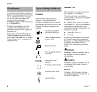
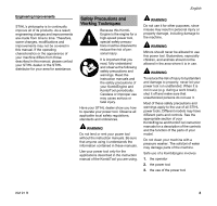
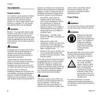
English KombiSystem In the STIHL KombiSystem a number of different KombiEngines and KombiTools can be combined to produce a power tool. In this instruction manual the functional unit formed by the KombiEngine and KombiTool is referred to as the power tool. Therefore, the separate instruction manuals for the KombiEngine and KombiTool should be used together for the power tool. Always read and and make sure you understand both instruction manuals before using your power tool for the first time and keep them in a safe place for future reference. Guide to Using this Manual Pictograms The meanings of the pictograms attached to or embossed on the machine are explained in this manual. Depending on the model concerned, the following pictograms may be on your machine. Fuel tank for gasoline and engine oil mixture Press to operate decompression valve Manual fuel pump Symbols in Text Many operating and safety instructions are supported by illustrations. The individual steps or procedures described in the manual may be marked in different ways: N A bullet marks a step or procedure. A description of a step or procedure that refers directly to an illustration may contain item numbers that appear in the illustration. Example: N Loosen the screw (1). N Lever (2) ... In addition to the operating instructions, this manual may contain paragraphs that require your special attention. Such paragraphs are marked with the symbols and signal words described below: Press to operate manual fuel pump DANGER Indicates a hazardous situation that, if not avoided, will result in death or serious injury. Filler hole for gear lubricant Air intake summer mode Air intake winter mode Handle heating WARNING Indicates a hazardous situation that, if not avoided, could result in death or serious injury. NOTICE Indicates a risk of property damage, including damage to the machine or its individual components. 2 KM 91 R
-
 1
1 -
 2
2 -
 3
3 -
 4
4 -
 5
5 -
 6
6 -
 7
7 -
 8
8 -
 9
9 -
 10
10 -
11
-
12
-
13
-
14
-
15
-
16
-
17
-
18
-
19
-
20
-
21
-
22
-
23
-
24
-
25
-
26
-
27
-
28
-
29
-
30
-
31
-
32
-
33
-
34
-
35
-
36
-
37
-
38
-
39
-
40
-
41
-
42
-
43
-
44
-
45
-
46
-
47
-
48
-
49
-
50
-
51
-
52
-
53
-
54
-
55
-
56
-
57
-
58
-
59
-
60
-
61
-
62
-
63
-
64
 |
 |