Sub-Zero 685 Built-In Installation Guide - Page 6
Installation Specifications
 |
View all Sub-Zero 685 manuals
Add to My Manuals
Save this manual to your list of manuals |
Page 6 highlights
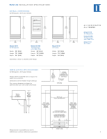
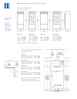
B U I LT- I N I N S TA L L A T I O N S P E C I F I C A T I O N S OVERALL DIMENSIONS Over-and-Under Models OVER-ANDUNDER Model 611 Model 611G with Glass Door Model 650 Model 650G with Glass Door 84" (2134) 84" (2134) 84" (2134) 84" (2134) 30" (762) 30" (762) 36" (914) 36" (914) 24" (610) Model 611 Width 30" (762) Height 84" (2138) Depth 24" (610) Model 611G with Glass Door Width 30" (762) Height 84" (2138) Depth 24" (610) Model 650 Width 36" (914) Height 84" (2138) Depth 24" (610) Model 650G with Glass Door Width 36" (914) Height 84" (2138) Depth 24" (610) Illustrations shown in stainless steel design. 3/8"(10) FRAME EXTENSION 90˚ 3 6 I N S TA L L AT I O N S P E C I F I C AT I O N S Over-and-Under Models 237/8" (606) BEHIND FRAME B Model 611 A) Rough Opening Width B) Min Door Clearance 291/2" (749) 301/8" (765) Model 611G A) Rough Opening Width B) Min Door Clearance 291/2" (749) 301/8" (765) Model 650 A) Rough Opening Width B) Min Door Clearance 351/2" (902) 361/16" (916) Model 650G A) Rough Opening Width B) Min Door Clearance 351/2" (902) 361/16" (916) Dimensions are for finished rough openings. Door swing clearances are based on stainless steel door and handle dimensions. 24" (610) ROUGH OPENING DEPTH EXTEND WATER LINE APPROX 36" (914) FROM BACK WALL SHUT-OFF VALVE TOP VIEW 7" (178) E LOCATE ELECTRICAL WITHIN SHADED AREA 6" (152) A ROUGH OPENING WIDTH 83" (2108) MIN HEIGHT REQUIRED TO FINISHED FLOORING (LEVELERS IN) 751/2" (1918) 833/4" (2127) ROUGH OPENING HEIGHT TO FINISHED FLOORING WITH STANDARD 11" (279) GRILLE LOCATE WATER SUPPLY WITHIN SHADED AREA 3" (76) 18" 6" (457) (152) W FRONT VIEW
-
 1
1 -
 2
2 -
 3
3 -
 4
4 -
 5
5 -
 6
6 -
 7
7 -
 8
8 -
 9
9 -
 10
10 -
 11
11 -
 12
12 -
13
-
14
-
15
-
16
-
17
-
18
-
19
-
20
-
21
-
22
-
23
-
24
 |
 |
