TEAC W-790R Owners Manual - Page 4
Features and Controls Fig. 7, Precautions - cassette deck
 |
View all TEAC W-790R manuals
Add to My Manuals
Save this manual to your list of manuals |
Page 4 highlights
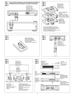
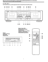
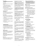
Precautions Environment Avoid using the deck in the following conditions: ● At high temperatures (near a heater, exposed to direct sunlight, etc.). ● At extremely low temperatures. ● Where there is excessive humidity. ● In a dusty atmosphere. ● Where power line voltage fluctuations are severe (in which case the use of a voltage regulator may be advisable). Cassette Tape (Fig.2) Tape Selection: For the automatic tape select function to work properly, metal and chrome (cobalt) tapes must have identification holes. Tape Handling: Do not store tapes in the following places: ● On top of heaters, exposed to direct sunlight or in any other places with high temperatures. ● Near speakers, on TV sets or amplifiers or where they would be exposed to strong magnetic fields. ● Where humidity is high and in dirty, dusty places. ● Avoid dropping or subjecting cassettes to excessive shocks. Connections (Fig.1) ● Turn off the power switches of all equipment before making connections. ● Read the instructions of each component you intend to use with the deck. LINE OUT terminals LINE OUT Terminals on the tape deck should be connected to the TAPE PLAY or LINE IN jacks on the amplifier/receiver. LINE IN terminals LINE IN Terminals on the tape deck should be connected to the REC OUT jacks on the amplifier/receiver. Power cord Be sure to connect the power cord to an AC outlet which supplies the correct voltage, as set by the voltage selector. IMPORTANT (for U.K. Customers) DO NOT cut off the mains plug from this equipment. If the plug fitted is not suitable for the power points in your home or the cable is too short to reach a power point, then obtain an appropriate safety approved extension lead or consult your dealer. If nonetheless the mains plug is cut off, remove the fuse and dispose of the plug immediately, to avoid a possible shock hazard by inadvertent connection to the mains supply. If this product is not provided with a mains plug, or one has to be fitted, then follow the instructions given below: IMPORTANT. DO NOT make any connection to the larger terminal which is marked with the letter E or by the safety earth symbol ç or coloured GREEN or GREEN-and-YELLOW. The wires in the mains lead on this product are coloured in accordance with the following code: BLUE: NEUTRAL BROWN: LIVE As these colours may not correspond with the coloured markings identifying the terminals in your plug proceed as follows: The wire which is coloured BLUE must be connected to the terminal which is marked with the letter N or coloured BLACK. The wire which is coloured BROWN must be connected to the terminal which is marked with the letter L or coloured RED. When replacing the fuse only a correctly rated approved type should be used and be sure to re-fit the fuse cover. IF IN DOUBT - CONSULT A COMPETENT ELECTRICIAN. *Dolby noise reduction and HX Pro headroom extension manufactured under license from Dolby Laboratories Licensing Corporation. HX Pro originated by Bang & Olufsen. "DOLBY", the double-D symbol ∂ and "HX PRO" are trademarks of Dolby Laboratories Licensing Corporation. Features and Controls (Fig. 7) Front Panel/Remote Control Unit 1 Power Switch Note: If you switch the power off, be sure to wait for more than 3 seconds before switching it on again. 2 DOLBY NR Select Switch OFF : Set to this position when you do not want to use any noise reduction system. B : Set to this position when making a recording using the Dolby B noise reduction system, or playing back tapes recorded with Dolby B NR. C : Set to this position when making a recording using the Dolby C noise reduction system, or playing back tapes recorded with Dolby C NR. 3 TIMER Switch (See page 8.) 4 REV (Reverse) MODE Switch (See page 5.) 5 Cassette Holder (TAPE I/TAPE II) (See page 5.) 6 SYNC REV (Reverse) Button (See page 7.) 7 REMOTE SENSOR (Infrared Signal Reception Window) 8 COUNTER CLEAR Button (TAPE I/TAPE II) Pressing the COUNTER CLEAR Button resets the multi-counter to "0000". 9 DUB (Dubbing) START Button (See page 6.) To enter the dubbing mode using the remote control, press the two DUB START buttons simultaneously. 0 Display Window ` Peak Level Meter 1 Direction & Pause Indicators 2 Multi Counter 3 SYNC REV Indicator 4 Mode Indicators 5 Dubbing Indicators q RECORD Button (TAPE II only) (See page 7.) To enter the record mode using the remote control, press the two RECORD buttons simultaneously. _ 4 _
-
 1
1 -
 2
2 -
 3
3 -
 4
4 -
 5
5 -
 6
6 -
 7
7 -
 8
8 -
 9
9 -
 10
10 -
11
-
12
-
13
-
14
-
15
-
16
-
17
-
18
-
19
-
20
-
21
-
22
-
23
-
24
-
25
-
26
-
27
-
28
-
29
-
30
-
31
-
32
-
33
-
34
-
35
-
36
-
37
-
38
-
39
-
40
-
41
-
42
 |
 |