TP-Link T2600G-52TS Jetstream L2 Managed SwitchUN Installation Guide - Page 19
Power
 |
View all TP-Link T2600G-52TS manuals
Add to My Manuals
Save this manual to your list of manuals |
Page 19 highlights
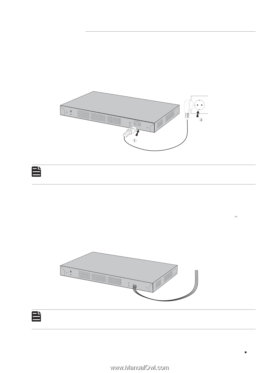
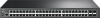
JetStream L2 Managed Switch 3.5 Power On For TL-SG5412F/T2500G-10TS/T2500G-10MPS/T2500-28TC/T2600G-18TS/T2600G-28TS/ T2600G-28MPS/T2600G-28SQ/ T2600G-52TS Plug the negative connector of the power cord directly into the power socket and plug the positive connector into an AC power outlet as the following figure shows. Make sure that the voltage of the power supply meets the requirement of the input voltage (100‑240V~ 50/60Hz). Figure 3-5 Connecting to the Power Supply 100-240V~50/60Hz 0.5A Note: The figure is to illustrate the application and principle. The provided plug and the socket in your region may differ from the figures above. For T2600G-28TS-DC Attach the power wires to the DC power input as the following figure shows. We recommend you use 22-14 AWG wires. Connect the positive pole of the DC power supply to the "+" end, and the negative pole to the "-" end. Make sure the power supply meets the requirement of the input (18-48V 1.2A). A disconnecting device like an isolating switch shall be installed and easily accessible. The disconnecting device shall have a contact separation at least equal to the minimum clearance for basic insulation. Figure 3-6 Connecting to the Power Supply To a disconnecting device and DC power supply Note: The figure is to illustrate the application and principle. The power wires and disconnecting device are not included with our product. If needed, you can purchase them separately. Connection 15
-
 1
1 -
2
-
3
-
4
-
5
-
6
-
7
-
8
-
9
-
10
-
11
-
12
-
13
-
 14
14 -
 15
15 -
 16
16 -
 17
17 -
 18
18 -
 19
19 -
 20
20 -
 21
21 -
 22
22 -
 23
23 -
 24
24
 |
 |