TP-Link TL-SG1008PE Installation Guide - Page 21
Connection
 |
View all TP-Link TL-SG1008PE manuals
Add to My Manuals
Save this manual to your list of manuals |
Page 21 highlights
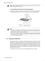
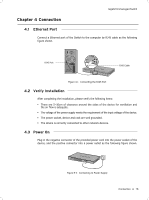
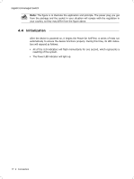
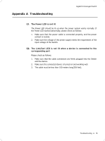
Gigabit Unmanaged Switch CCCCCCCCCC Connection 4444 Ethernet Port Connect a Ethernet port of the Switch to the computer by RJ45 cable as the following figure shown. RJ45 Port RJ45 Cable FFFFFFFFFFF Connecting the RJ45 Port 4444 Verify Installation After completing the installation, please verify the following items: ■■ There are 5~10cm of clearance around the sides of the device for ventilation and the air flow is adequate. ■■ The voltage of the power supply meets the requirement of the input voltage of the device. ■■ The power socket, device and rack are well grounded. ■■ The device is correctly connected to other network devices. 4444 Power On Plug in the negative connector of the provided power cord into the power socket of the device, and the positive connector into a power outlet as the following figure shown. FFFFFFFFFFF Connecting to Power Supply Connection 16
-
 1
1 -
2
-
3
-
4
-
5
-
6
-
7
-
8
-
9
-
10
-
11
-
12
-
13
-
14
-
15
-
 16
16 -
 17
17 -
 18
18 -
 19
19 -
 20
20 -
 21
21 -
 22
22 -
 23
23 -
 24
24 -
 25
25 -
 26
26 -
27
-
28
 |
 |
