TP-Link TL-SL2218 TL-SL2218 V1 IG 7106504093 - Page 12
Installation Tools, Product Installation
 |
View all TP-Link TL-SL2218 manuals
Add to My Manuals
Save this manual to your list of manuals |
Page 12 highlights
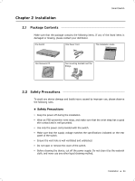
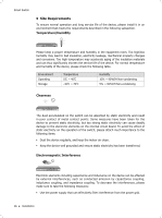
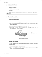
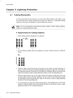
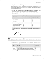
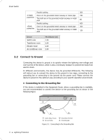
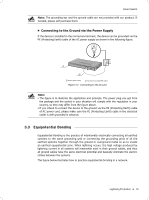
Smart Switch 2222 Installation Tools ■■ Phillips screwdriver ■■ ESD-preventive wrist wrap ■■ Cables Note: These tools are not provided with our product. If needed, please self purchase them. 2222 Product Installation ■■ Desktop Installation To install the device on the desktop, please follow the steps: 111Set the device on a flat surface strong enough to support the entire weight of the device with all fittings. 222Remove the adhesive backing papers from the rubber feet. 333Turnover the device and attach the supplied rubber feet to the recessed areas on the bottom at each corner of the device. Feet Bottom of the Device Notch FFFFFFFFFFF Desktop Installation ■■ Rack Installation To install the device in an EIA standard-sized, 19-inch rack, follow the instructions described below: 111Check the grounding and stability of the rack. 222Secure the supplied rack-mounting brackets to each side of the device with supplied screws, as illustrated in the following figure. 07 Installation
-
 1
1 -
2
-
3
-
4
-
5
-
6
-
 7
7 -
 8
8 -
 9
9 -
 10
10 -
 11
11 -
 12
12 -
 13
13 -
 14
14 -
 15
15 -
 16
16 -
 17
17 -
18
-
19
-
20
-
21
-
22
-
23
-
24
-
25
-
26
-
27
-
28
 |
 |
