TP-Link TL-SL3452 User Guide - Page 70
Configuring MSTP Instances
 |
UPC - 845973020507
View all TP-Link TL-SL3452 manuals
Add to My Manuals
Save this manual to your list of manuals |
Page 70 highlights
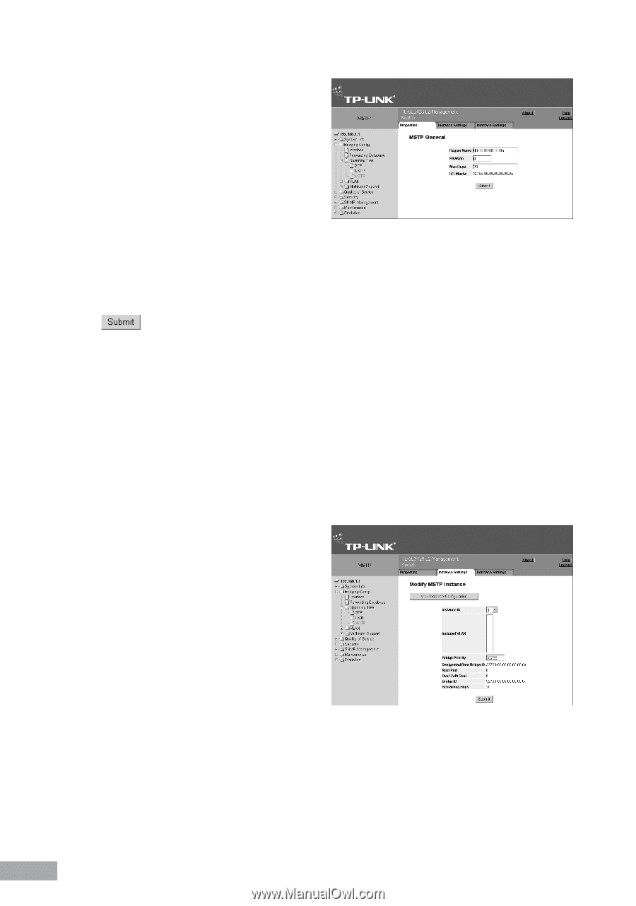
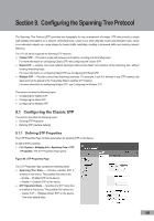
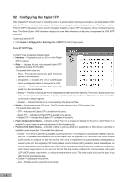
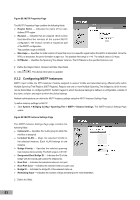
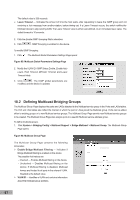
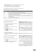
Figure 89: MSTP Properties Page The MSTP Properties Page contains the following fields: Region Name - Indicates the name of the user- defined STP region. Revision - Indicates that an unsigned 16-bit number that identifies the revision of the current MSTP configuration. The revision number is required as part of the MSTP configuration. The possible range is 0-65535. Max Hops - Specifies the total number of hops that occur in a specific region before the BPDU is discarded. Once the BPDU is discarded, the port information is aged out. The possible field range is 1-40. The default value is 20 hops. IST Master - Identifies the Spanning Tree Master instance. The IST Master is the specified instance root. 2. Define the Region Name, Revision and Max Hops fields. 3. Click . The device information is updated. 9.3.2 Configuring MSTP Instances MSTP maps VLANs into STP instances. Packets assigned to various VLANs are transmitted along different paths within Multiple Spanning Tree Regions (MST Regions). Regions are one or more Multiple Spanning Tree bridges by which frames can be transmitted. In configuring MSTP, the MST region to which the device belongs is defined. A configuration consists of the name, revision, and region to which the device belongs. Network administrators can define the MSTP instance settings using the MSTP Instance Settings Page. To define instance settings for MSTP: 1. Click System > Bridging Config > Spanning Tree > MSTP > Instance Settings. The MSTP Instance Settings Page opens: Figure 90: MSTP Instance Settings Page The MSTP Instance Settings Page page contains the following fields: Instance ID - Specifies the VLAN group to which the interface is assigned. Included VLAN - Maps the selected VLANs to the selected instance. Each VLAN belongs to one instance. Bridge Priority - Specifies the selected spanning tree instance device priority. The field range is 0-61440 Designated Root Bridge ID - Indicates the ID of the bridge with the lowest path cost to the instance ID. Root Port - Indicates the selected instance's root port. Root Path Cost - Indicates the selected instance's path cost. Bridge ID - Indicates the bridge ID of the selected instance. Remaining Hops - Indicates the number of hops remaining to the next destination. 2. Define the fields. 63
-
 1
1 -
2
-
3
-
4
-
5
-
6
-
7
-
8
-
9
-
10
-
11
-
12
-
13
-
14
-
15
-
16
-
17
-
18
-
19
-
20
-
21
-
22
-
23
-
24
-
25
-
26
-
27
-
28
-
29
-
30
-
31
-
32
-
33
-
34
-
35
-
36
-
37
-
38
-
39
-
40
-
41
-
42
-
43
-
44
-
45
-
46
-
47
-
48
-
49
-
50
-
51
-
52
-
53
-
54
-
55
-
56
-
57
-
58
-
59
-
60
-
61
-
62
-
63
-
64
-
 65
65 -
 66
66 -
 67
67 -
 68
68 -
 69
69 -
 70
70 -
 71
71 -
 72
72 -
 73
73 -
 74
74 -
 75
75 -
76
-
77
-
78
-
79
-
80
-
81
-
82
-
83
-
84
-
85
-
86
-
87
-
88
-
89
-
90
-
91
-
92
-
93
-
94
-
95
-
96
-
97
-
98
-
99
-
100
-
101
-
102
-
103
-
104
-
105
-
106
-
107
-
108
-
109
-
110
-
111
-
112
-
113
-
114
-
115
-
116
-
117
-
118
-
119
-
120
 |
 |