TRENDnet TV-IP344PI Users Guide - Page 5
Installation - reset
 |
View all TRENDnet TV-IP344PI manuals
Add to My Manuals
Save this manual to your list of manuals |
Page 5 highlights
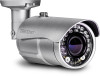
TRENDnet User's Guide Camera Connectors GPIO Port Speaker Out Microphone In Power Connector Ethernet /PoE Port TV‐IP344PI Installation Hardware Installation Viewing Angle Choose the location where has good angle to shoot the image you expect to see. The motion detection area should also be considered when installing the camera. Bracket Installation Turn and lock the bracket into the mounting hole of IP camera. Use screws to fix the bracket to ceiling or wall, and turn the knob tightly to fix the angle of camera. Power Connector: Connects the power adapter to supply power to the camera if using non‐PoE connection Microphone In: Connects an external microphone to receive the on‐the‐spot sound where the camera is installed. Ethernet/PoE Port: Plugs the network cable to connect to your local area network (LAN). If you are using the PoE, you must have the network cable connect to your PoE switch or PoE Injector. GPIO Port: Connect external device. Please refer to I/O setting paragraph. It's also used for IP camera reset. Please refer to Factory Default paragraph. Speaker Out: Connects an external audio device (such as the active speaker) to deliver sound via the camera. LED Indicator The green LED will be flash when power on the camera and if there is the data transmission. Power On LED © Copyright 2016 TRENDnet. All Rights Reserved. 3
-
 1
1 -
 2
2 -
 3
3 -
 4
4 -
 5
5 -
 6
6 -
 7
7 -
 8
8 -
 9
9 -
 10
10 -
 11
11 -
12
-
13
-
14
-
15
-
16
-
17
-
18
-
19
-
20
-
21
-
22
-
23
-
24
-
25
-
26
-
27
-
28
-
29
-
30
-
31
-
32
-
33
-
34
-
35
-
36
-
37
-
38
-
39
-
40
 |
 |
