TRENDnet TV-IP400 User's Guide - Page 12
Power Connector, Reset Button, LAN Port
 |
UPC - 710931303117
View all TRENDnet TV-IP400 manuals
Add to My Manuals
Save this manual to your list of manuals |
Page 12 highlights
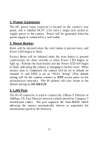
1. Power Connector The DC power input connector is located on the camera's rear panel, and is labeled DC5V 2.5A with a single jack socket to supply power to the camera. Power will be generated when the power supply is connected to a wall outlet. 2. Reset Button Reset will be initiated when the reset button is pressed once, and Power LED begins to flash. Factory Reset will be initiated when the reset button is pressed continuously for three seconds or when Power LED begins to light up. Release the reset button and the Power LED will begin to flash, indicating the camera is changing to factory reset. When factory reset is completed, the camera will be set to default on channel 11 and SSID is set as "NULL String" (This default setting will let the camera connect to ANY access point on the infrastructure network). The IP address will also return to the default setting as 192.168.0.20. 3. LAN Port The RJ-45 connector is used to connect the 10Base-T Ethernet or 100Base-TX Fast Ethernet network (which should be Category 5 twisted-pair cable). The port supports the Auto-MDIX which allowing the camera automatically detects or negotiates the transmission speed of the Network. 11
-
 1
1 -
2
-
3
-
4
-
5
-
6
-
 7
7 -
 8
8 -
 9
9 -
 10
10 -
 11
11 -
 12
12 -
 13
13 -
 14
14 -
 15
15 -
 16
16 -
 17
17 -
18
-
19
-
20
-
21
-
22
-
23
-
24
-
25
-
26
-
27
-
28
-
29
-
30
-
31
-
32
-
33
-
34
-
35
-
36
-
37
-
38
-
39
-
40
-
41
-
42
-
43
-
44
-
45
-
46
-
47
-
48
-
49
-
50
-
51
-
52
-
53
-
54
-
55
-
56
-
57
-
58
-
59
-
60
-
61
-
62
-
63
-
64
-
65
-
66
-
67
-
68
-
69
-
70
-
71
-
72
-
73
-
74
-
75
-
76
-
77
-
78
-
79
-
80
-
81
-
82
-
83
-
84
-
85
-
86
-
87
-
88
-
89
-
90
-
91
-
92
-
93
-
94
-
95
-
96
-
97
-
98
-
99
-
100
-
101
-
102
-
103
-
104
-
105
-
106
-
107
-
108
-
109
-
110
-
111
-
112
-
113
 |
 |
