Thermador PRD606WCSG Installation Instructions - Page 18
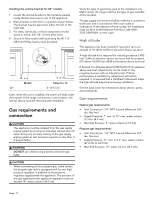
Gas requirements and, connection
 |
View all Thermador PRD606WCSG manuals
Add to My Manuals
Save this manual to your list of manuals |
Page 18 highlights
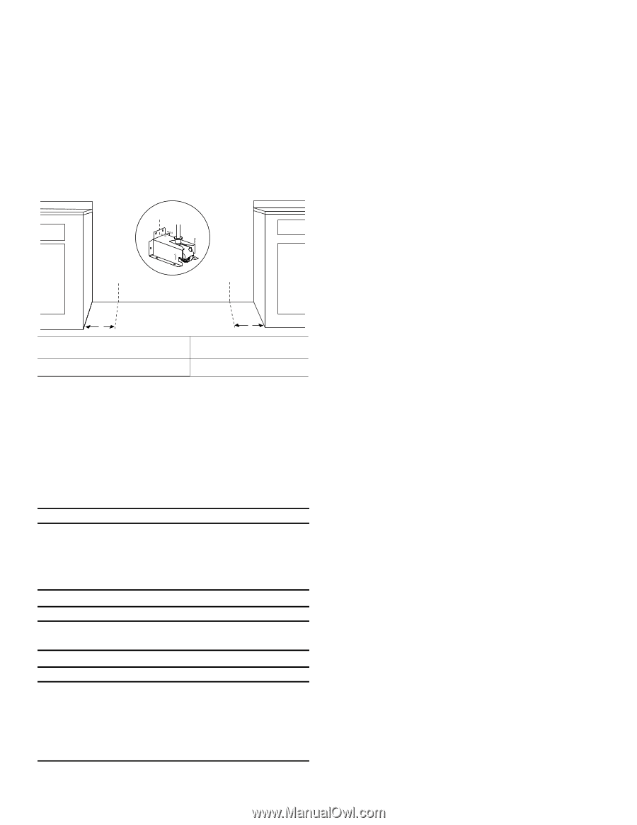
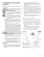
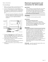
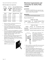
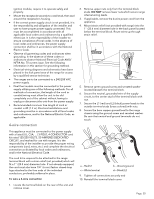
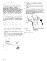
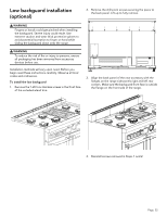
Installing the anti-tip bracket for 60'' models 1. Locate the anti-tip bracket in the literature packet, inside the box that was on top of the appliance. 2. Place bracket on the floor in a position shown below. The bracket may be placed on either the left or the right side. 3. For walls, wall studs, or floors composed of solid wood or metal, drill 1/8'' (3 mm) pilot holes. 4. Secure to floor and/or wall stud using the (4) 1 ½'' (38 mm) Phillips head screws provided. CL CL CL x Model 60'' x Value for 'X' 2'' (51 mm) Later, when the unit is installed, the caster will slide under the bracket. If the range is moved to a new location, the anti-tip device must be removed and reinstalled. Gas requirements and connection 9 CAUTION The appliance must be isolated from the gas supply piping system by closing its individual manual shut-off valve during any pressure testing of the gas supply piping system at test pressures equal to or less than 1/ 2 psig (3.5kPa.). 9 WARNING DO NOT use a flame of any kind to check for gas leaks. Verify the type of gas being used at the installation site. Make certain the range matches the type of gas available at this location. The gas supply connections shall be made by a competent technician and in accordance with local codes or ordinances. In the absence of local codes, the installation must conform to the National Fuel Gas Code ANSI Z223.1/NFPA54- current issue. High altitude This appliance has been tested for operation up to an altitude of 10,100 ft (3,078 m) elevation above sea level. A high altitude kit is required for natural gas above 5,400 feet (1,646 m) elevation above sea level, and for propane (LP) above 10,000 feet (3048 m) elevation above sea level. If desired, for altitudes above 2,000 feet (610 m) elevation above sea level, adjustments can be made to the rangetop burners with an adjustment kit. If flame performance is satisfactory, adjustment will not be required. It is required that a Certified Professional make the high altitude adjustments during installation. See the back cover for information about service, parts, and accessories. Gas requirements Natural gas requirements: • Inlet Connection: 1/2'' NPT internal (Minimum 3/4'' dia. flex line) • Supply Pressure: 7'' min. to 14'' max. water column (17.4 to 34.9 mb) • Manifold Pressure: 5'' water column (12.5 mb) Propane gas requirements: • Inlet Connection: 1/2'' NPT internal (Minimum 3/4'' dia. flex line) • Supply Pressure: 11'' min. to 14'' max. water column (27.4 mb to 34.9 mb) • Manifold Pressure: 10'' water column (24.9 mb) 9 CAUTION When connecting unit to propane gas, make certain the propane gas tank is equipped with its own high pressure regulator in addition to the pressure regulator supplied with the appliance. The pressure of the gas supplied to the appliance regulator must not exceed 14" water column (34.9 mb). Page. 17
-
 1
1 -
2
-
3
-
4
-
5
-
6
-
7
-
8
-
9
-
10
-
11
-
12
-
 13
13 -
 14
14 -
 15
15 -
 16
16 -
 17
17 -
 18
18 -
 19
19 -
 20
20 -
 21
21 -
 22
22 -
 23
23 -
24
-
25
-
26
-
27
-
28
-
29
-
30
-
31
-
32
-
33
-
34
-
35
-
36
-
37
-
38
-
39
-
40
-
41
-
42
-
43
-
44
-
45
-
46
-
47
-
48
-
49
-
50
-
51
-
52
-
53
-
54
-
55
-
56
-
57
-
58
-
59
-
60
-
61
-
62
-
63
-
64
-
65
-
66
-
67
-
68
-
69
-
70
-
71
-
72
-
73
-
74
-
75
-
76
-
77
-
78
-
79
-
80
-
81
-
82
-
83
-
84
 |
 |