Thermador PRD606WCSG Installation Instructions - Page 19
Electrical requirements and, connection for GAS models
 |
View all Thermador PRD606WCSG manuals
Add to My Manuals
Save this manual to your list of manuals |
Page 19 highlights
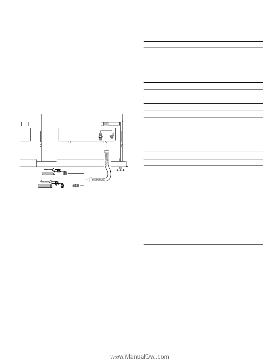
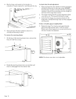
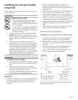
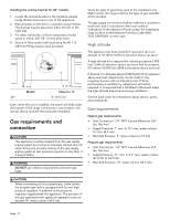
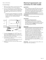
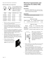
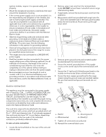
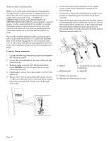
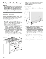
Gas connection To connect the gas 1. Make sure the gas supply is turned off at the manual shut-off valve before connecting the appliance. 2. Use a ¾'' (19 mm) flex line to connect between the gas supply and the appliance gas inlet. The gas supply line connection is located at the lower right portion. The appliance gas inlet connection is ½'' (12.7 mm) NPT. • Use caution to avoid crimping the ¾'' (19 mm) flex line when making bends. Suggested length of flex line is 48" (1219 mm); however, please check local codes for your area's requirements before installation. ¾" (19) external threads ½" (12.7) internal threads { Electrical requirements and connection for GAS models 9 WARNING Before installing, turn power OFF at the service panel. Lock service panel to prevent power from being turned ON accidentally. Always disconnect appliance from the electric supply either by disconnecting power cord or shutting off the breaker at the service panel before servicing the appliance. 9 WARNING This product must be properly grounded. 9 WARNING Electrical grounding instructions This appliance is equipped with a three-prong grounding plug for your protection against shock hazard and should be plugged directly into a properly grounded receptacle. DO NOT cut or remove the grounding prong from this plug. ¾" (19) Flex line inches (mm) 3. Use pipe sealing compound or Teflon® tape on the pipe threads. DO NOT apply sealing compound or tape to flare fittings. Take care not to apply excessive pressure when tightening the fittings. 4. Leak testing of the appliance shall be in accordance with the following instructions: • Turn on gas and check supply line connections for leaks using a soap and water solution. 5. Bubbles forming indicate a gas leak. Repair all leaks immediately. 9 CAUTION Improper grounding or reverse polarization will cause malfunction (such as continuous sparking of the burner igniters). This can damage the appliance and can create a condition of shock hazard. If the dedicated circuit is not correctly grounded and polarized, it is the responsibility and obligation of the installer and user to have the existing receptacle changed to a properly dedicated grounded and polarized receptacle. This must be accomplished in accordance with all applicable local codes and ordinances by a qualified electrician. In the absence of local codes and ordinances, the receptacle replacement shall be in accordance with the National Electric Code. INSTALLER - show the owner the location of the circuit breaker. Mark it for easy reference. Page. 18
-
 1
1 -
2
-
3
-
4
-
5
-
6
-
7
-
8
-
9
-
10
-
11
-
12
-
13
-
 14
14 -
 15
15 -
 16
16 -
 17
17 -
 18
18 -
 19
19 -
 20
20 -
 21
21 -
 22
22 -
 23
23 -
 24
24 -
25
-
26
-
27
-
28
-
29
-
30
-
31
-
32
-
33
-
34
-
35
-
36
-
37
-
38
-
39
-
40
-
41
-
42
-
43
-
44
-
45
-
46
-
47
-
48
-
49
-
50
-
51
-
52
-
53
-
54
-
55
-
56
-
57
-
58
-
59
-
60
-
61
-
62
-
63
-
64
-
65
-
66
-
67
-
68
-
69
-
70
-
71
-
72
-
73
-
74
-
75
-
76
-
77
-
78
-
79
-
80
-
81
-
82
-
83
-
84
 |
 |