Thermador PRD606WCSG Installation Instructions - Page 22
wire lead connection
 |
View all Thermador PRD606WCSG manuals
Add to My Manuals
Save this manual to your list of manuals |
Page 22 highlights
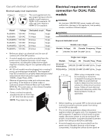
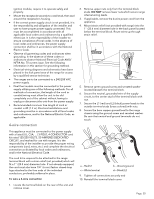
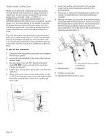
3-wire lead connection Where local codes and ordinances permit grounding through neutral, and conversion of supply to 4-wire is impractical, the unit may be connected to the power supply with a Listed (UL, CSA, ...) 3-POLE, 3CONDUCTOR cord kit rated 125/250 VOLTS, 50 AMPERES DEDICATED CIRCUIT, and marked for use with ranges. It is the responsibility of the installer to provide the proper wiring components (cord, wires, etc.) and complete the electrical connection as dictated by local codes and ordinances, and/or the National Electrical Code. The cord kit must be attached to the range back panel with a strain relief which will fit a 1" (25.4 mm) diameter hole. If not already equipped, the cord must also have 1/4'' (6 mm) faston closed-loop lugs attached to the free ends of the individual conductors, preferably soldered in place. To wire a 3-wire connection 1. Locate the small bag with white jumper wire located in the literature packet. 2. Locate the terminal block on the rear of the unit and remove cover. 3. Remove upper nuts only from the terminal block studs. DO NOT remove nuts which secure range internal wiring leads. 4. If applicable, remove the 4-wire power cord from the appliance. 5. Mount strain relief (not provided with range) into the 1'' (25.4 mm) diameter hole in the back panel located below the terminal block. Route wires up through strain relief. 6. Secure the neutral, grounded wire of the supply circuit, to the center stud (silver colored) of the terminal block. 7. Secure the L1 (red) and L2 (black) power leads to the outside corresponding terminal block studs (brass colored). 8. Remove the green ground screw and serrated washer located beneath the terminal block. Screw one end of the included white jumper wire to the chassis beneath the terminal block with the green ground screw. Secure the other end of the wire to the center stud of the terminal block with nut. d c a b a - Red/L1 c - White/neutral b - Ground link wire provided in small bag. d - Black/L2 9. Tighten nuts securely. 10. Reinstall the terminal block cover. Page. 21
-
 1
1 -
2
-
3
-
4
-
5
-
6
-
7
-
8
-
9
-
10
-
11
-
12
-
13
-
14
-
15
-
16
-
 17
17 -
 18
18 -
 19
19 -
 20
20 -
 21
21 -
 22
22 -
 23
23 -
 24
24 -
 25
25 -
 26
26 -
 27
27 -
28
-
29
-
30
-
31
-
32
-
33
-
34
-
35
-
36
-
37
-
38
-
39
-
40
-
41
-
42
-
43
-
44
-
45
-
46
-
47
-
48
-
49
-
50
-
51
-
52
-
53
-
54
-
55
-
56
-
57
-
58
-
59
-
60
-
61
-
62
-
63
-
64
-
65
-
66
-
67
-
68
-
69
-
70
-
71
-
72
-
73
-
74
-
75
-
76
-
77
-
78
-
79
-
80
-
81
-
82
-
83
-
84
 |
 |
