Toro 20330 Service Manual - Page 104
up and down on the crankshaft Fig. 176.
 |
UPC - 021038203300
View all Toro 20330 manuals
Add to My Manuals
Save this manual to your list of manuals |
Page 104 highlights
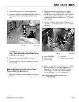
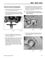
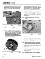
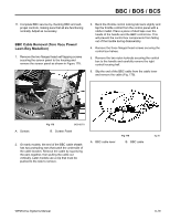
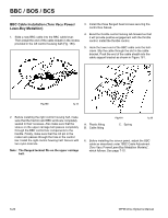
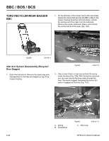
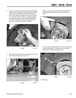
BBC / BOS / BCS 6. Install the BBC flywheel onto the crankshaft, making certain that the slots in the BBC flywheel align with the bumps on the bottom of the self-propel pulley (Fig. 175). A B 7. Press the bearings into the bearing block, using an arbor press. Press only on the outer race, otherwise bearing damage will result (use an appropriately sized arbor or a 1-1/8" (28mm) socket to press the bearing into the block). 8. Make sure that the foam rubber anti-vibration pads are in place on the brake drum and assemble the brake drum bearing block and BBC screws onto the crankshaft as shown in Figure 177. Secure with the crankshaft nut. Note: Crankshaft nut torque: 45 - 70 ft-lbs. (61 - 95 Nm) A. Bumps Fig 175 B. Slots 3428-0117 Note: If the crankshaft nut is tightened with these bumps misaligned, the boss at the bottom of the keyway on the self-propel pulley will break and the self-propel pulley will be free to slide up and down on the crankshaft (Fig. 176). This can result in noisy operation, premature belt wear, and belt jumping. Fig 177 MVC-726 CAUTION! As with disassembly, the flywheel can be wedged to tighten the nut. Make sure the bumps in the self-propel pulley stay engaged with the flywheel or the pulley will be damaged. Note: Make sure that the blade bolts are properly aligned before tightening the crankshaft nut. 9. Install the BBC cover with the four flanged head selftapping screws. A 10. Install the BBC screen, the blade spacer, the blade, and the anti-scalp cup onto the BBC screw and secure with the two flanged nylon locknuts. Torque to 300 in-lbs. (37 Nm). A. Boss Fig 176 3428-0116 Note: Blade locknut torque: 300 in-lbs. (37 Nm) 6-18 WPM Drive Systems Manual
-
 1
1 -
2
-
3
-
4
-
5
-
6
-
7
-
8
-
9
-
10
-
11
-
12
-
13
-
14
-
15
-
16
-
17
-
18
-
19
-
20
-
21
-
22
-
23
-
24
-
25
-
26
-
27
-
28
-
29
-
30
-
31
-
32
-
33
-
34
-
35
-
36
-
37
-
38
-
39
-
40
-
41
-
42
-
43
-
44
-
45
-
46
-
47
-
48
-
49
-
50
-
51
-
52
-
53
-
54
-
55
-
56
-
57
-
58
-
59
-
60
-
61
-
62
-
63
-
64
-
65
-
66
-
67
-
68
-
69
-
70
-
71
-
72
-
73
-
74
-
75
-
76
-
77
-
78
-
79
-
80
-
81
-
82
-
83
-
84
-
85
-
86
-
87
-
88
-
89
-
90
-
91
-
92
-
93
-
94
-
95
-
96
-
97
-
98
-
 99
99 -
 100
100 -
 101
101 -
 102
102 -
 103
103 -
 104
104 -
 105
105 -
 106
106 -
 107
107 -
 108
108 -
 109
109 -
110
-
111
-
112
-
113
-
114
-
115
-
116
-
117
-
118
-
119
-
120
-
121
-
122
-
123
-
124
-
125
-
126
-
127
-
128
-
129
-
130
-
131
-
132
-
133
-
134
-
135
-
136
-
137
-
138
-
139
-
140
-
141
-
142
-
143
-
144
 |
 |
