Toro 20330 Service Manual - Page 99
Bellcrank System Assembly Toro Vacu, Power/Lawn-Boy Medallion
 |
UPC - 021038203300
View all Toro 20330 manuals
Add to My Manuals
Save this manual to your list of manuals |
Page 99 highlights
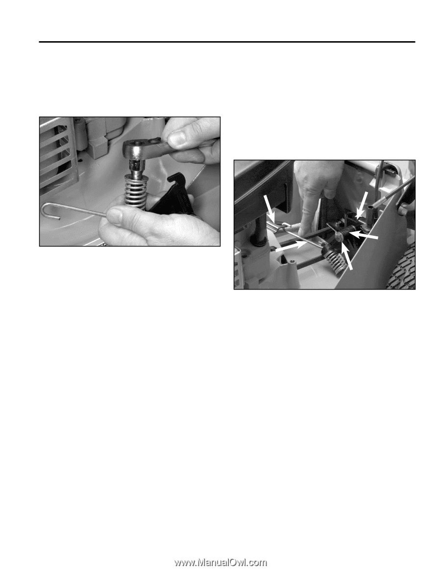
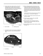
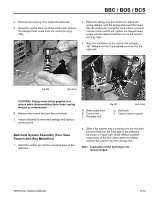
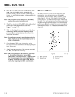
BBC / BOS / BCS 4. Remove the bushing from inside the bellcrank. 5. Using the control link to hold the control pin, remove the flanged head screw from the control pin (Fig. 166). 2. Place the spring onto the control pin. Place the spring retainer onto the spring and insert the screw into the control pin. Using the control link to prevent rotation of the control pin, tighten the flanged head screw until the retainer bottoms out on the control pin (Fig. 166). 3. Note the orientation of the control link in Figure 167. Make sure that it is installed correctly into the bellcrank. A E Fig 166 3428-0093 CAUTION! Always wear safety goggles and gloves when disassembling items under spring tension or compression. 6. Remove the control link from the control pin. 7. Inspect all parts for wear and damage and replace as necessary. Bellcrank System Assembly (Toro Vacu Power/Lawn-Boy Medallion) 1. Insert the control pin into the recessed area on the bellcrank. D B C A. Brake plate lever B. Control link C. Shoulder bolt Fig 167 3428-0088 D. Bellcrank E. Cable bracket support 4. Slide a flat washer and a bushing onto the shoulder bolt and slide into the front side of the bellcrank as shown in Figure 000. (3428-0088) Complete reassembly of the bell crank system by sliding another flat washer onto the carriage bolt. Note: Lubrication of the bushing is not recommended. WPM Drive Systems Manual 6-13
-
 1
1 -
2
-
3
-
4
-
5
-
6
-
7
-
8
-
9
-
10
-
11
-
12
-
13
-
14
-
15
-
16
-
17
-
18
-
19
-
20
-
21
-
22
-
23
-
24
-
25
-
26
-
27
-
28
-
29
-
30
-
31
-
32
-
33
-
34
-
35
-
36
-
37
-
38
-
39
-
40
-
41
-
42
-
43
-
44
-
45
-
46
-
47
-
48
-
49
-
50
-
51
-
52
-
53
-
54
-
55
-
56
-
57
-
58
-
59
-
60
-
61
-
62
-
63
-
64
-
65
-
66
-
67
-
68
-
69
-
70
-
71
-
72
-
73
-
74
-
75
-
76
-
77
-
78
-
79
-
80
-
81
-
82
-
83
-
84
-
85
-
86
-
87
-
88
-
89
-
90
-
91
-
92
-
93
-
 94
94 -
 95
95 -
 96
96 -
 97
97 -
 98
98 -
 99
99 -
 100
100 -
 101
101 -
 102
102 -
 103
103 -
 104
104 -
105
-
106
-
107
-
108
-
109
-
110
-
111
-
112
-
113
-
114
-
115
-
116
-
117
-
118
-
119
-
120
-
121
-
122
-
123
-
124
-
125
-
126
-
127
-
128
-
129
-
130
-
131
-
132
-
133
-
134
-
135
-
136
-
137
-
138
-
139
-
140
-
141
-
142
-
143
-
144
 |
 |