Toro 20330 Service Manual - Page 47
Belt Service - Front Wheel Drive Models - operator s manual
 |
UPC - 021038203300
View all Toro 20330 manuals
Add to My Manuals
Save this manual to your list of manuals |
Page 47 highlights
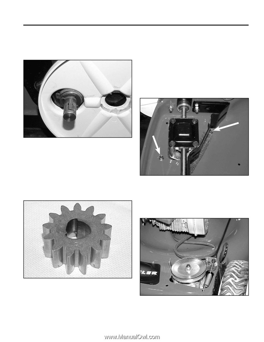
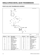
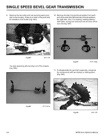
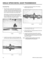
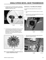
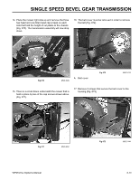
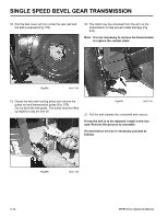
SINGLE SPEED BEVEL GEAR TRANSMISSION 7. Coat the axle, key, and spring with #2 molybendum disulfide base grease or anti-seize compound before installing the pinion (Fig. 055). Belt Service - Front Wheel Drive Models To replace the self-propelled drive belt, proceed as follows: 1. Drain the fuel and oil and tip the mower on its right side. 2. Remove the two screws securing the belt cover from under the housing (Fig. 057). Fig 055 MVC-472 8. The wheel pinion is marked with an R and L for right and left. Identify right and left from the operator's position (Fig. 056). On the right side, the letter R should face out. The letter L should face out on the left side. If the wheel pinions are reversed, the wheels will not drive. Fig 057 MVC-482 3. Slip the belt off the transmission pulley and push it towards the engine (Fig. 058). R Fig 056 MVC-474 Note: For more information on the wheel clutch see Section 5, Wheel Pinion Clutch. WPM Drive Systems Manual Fig 058 MVC-487 3-9
-
 1
1 -
2
-
3
-
4
-
5
-
6
-
7
-
8
-
9
-
10
-
11
-
12
-
13
-
14
-
15
-
16
-
17
-
18
-
19
-
20
-
21
-
22
-
23
-
24
-
25
-
26
-
27
-
28
-
29
-
30
-
31
-
32
-
33
-
34
-
35
-
36
-
37
-
38
-
39
-
40
-
41
-
 42
42 -
 43
43 -
 44
44 -
 45
45 -
 46
46 -
 47
47 -
 48
48 -
 49
49 -
 50
50 -
 51
51 -
 52
52 -
53
-
54
-
55
-
56
-
57
-
58
-
59
-
60
-
61
-
62
-
63
-
64
-
65
-
66
-
67
-
68
-
69
-
70
-
71
-
72
-
73
-
74
-
75
-
76
-
77
-
78
-
79
-
80
-
81
-
82
-
83
-
84
-
85
-
86
-
87
-
88
-
89
-
90
-
91
-
92
-
93
-
94
-
95
-
96
-
97
-
98
-
99
-
100
-
101
-
102
-
103
-
104
-
105
-
106
-
107
-
108
-
109
-
110
-
111
-
112
-
113
-
114
-
115
-
116
-
117
-
118
-
119
-
120
-
121
-
122
-
123
-
124
-
125
-
126
-
127
-
128
-
129
-
130
-
131
-
132
-
133
-
134
-
135
-
136
-
137
-
138
-
139
-
140
-
141
-
142
-
143
-
144
 |
 |