Toshiba 42HP95 Owner's Manual - English - Page 11
TV back panel connections - tv will not power up
 |
View all Toshiba 42HP95 manuals
Add to My Manuals
Save this manual to your list of manuals |
Page 11 highlights
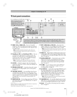
Chapter 2: Connecting your TV TV back panel connections For an explanation of cable types, see page 12. Before connecting the external 56 device to the TV, remove the applicable panel cover by squeezing the tabs in the direction of the arrow (%) and pulling the cover. TV back 8 0 7 9 !¡ !™ 1 2 34 !£ Wall outlet 120V AC 60Hz Power cord* * The power cord supplied with this product is to be used in United States and Canada only. If this product is used in another country, use a power cord which confirms to the law or regulations of that country. Do not remove the noise filter from the power cord. The noise filter is to reduce the interference in image or sound of other electronic equipment. 1 VIDEO 1 IN and VIDEO 2 IN - Two sets of standard (composite) video and standard audio inputs plus optional S-video inputs for connecting devices with composite video or S-video output. Note: Standard (composite) video and S-video cables carry only video information; separate audio cables are required for a complete connection. 2 ColorStream® HD-1 and ColorStream® HD-2 - Two sets of ColorStream® high-definition component video and standard stereo audio inputs for connecting devices with component video output, such as a Toshiba DVD player with ColorStream®. See pages 16 and 18. Note: Component video cables carry only video information; separate audio cables are required for a complete connection. 3 A/V OUT - Standard composite video and analog audio outputs for connecting a VCR for editing and dubbing. See page 19 for details. 4 VARIABLE AUDIO OUT - Standard analog audio outputs for connecting an analog amplifier with external speakers. See page 21. 5 TheaterNet™ (IR) OUT - For controlling infrared remotecontrolled devices through the TV. You can connect up to two devices with either one of the enclosed IR blaster cables, and then control the devices using the TV's IR pass-through or TheaterNet™ (on-screen device control) features. See pages 22 and 47. 6 HDMI AUDIO IN - For use when connecting a DVI device with analog audio output to the HDMI input. See page 20. Also see item 8 below. ___________ HDMI, the HDMI logo and High-Definition Multimedia Interface are trademarks or registered trademarks of HDMI Licensing LLC. CableCARD is a trademark of Cable Television Laboratories, Inc. 7 ANT 1 (CABLE) IN and ANT 2 IN - Two inputs that support analog (NTSC) and digital (ATSC) off-air antenna signals and analog and digital (QAM) Cable TV signals. Note: If you have an antenna only, connect it to ANT 1. If you have both cable TV and an antenna, connect the cable TV to ANT 1 and the antenna to ANT 2. 8 HDMI™ IN - High-Definition Multimedia Interface input receives digital audio and uncompressed digital video from an HDMI device or uncompressed digital video from a DVI device. See page 20. 9 DIGITAL AUDIO OUT - Optical audio output in Dolby Digital or PCM (pulse-code modulation) format for connecting an external Dolby Digital decoder, amplifier, A/V receiver, or home theater system with optical audio input. See page 21. 0 G-LINK™ - For use with one of the enclosed IR blaster/ G-LINK™ cables to enable the TV Guide On Screen™ recording features. See page 26. !¡ (2) IEEE1394 - Two bi-directional digital IEEE1394 ports for connecting multiple devices with compressed digital video. Because these ports are bi-directional, they can be used for playback and recording. You can control your IEEE1394 devices using the TV's TheaterNet on-screen device control icons. See pages 23-25 and 47. Note: IEEE1394 cable carries both audio and video information; separate audio cables are not required. !™ CableCARD™ slot - For use with a digital security card and digital cable TV service (provided by your local cable operator) to view encrypted digital programming. See pages 13 and 53. !£ PC IN - For use when connecting a personal computer (PC). See page 27. Copyright © 2005 TOSHIBA CORPORATION. All rights reserved. 11 #01E_010-012_4250HP95 11 Black (E) 42/50HP95 *web 213:276 05.9.12, 10:05 PM
-
 1
1 -
2
-
3
-
4
-
5
-
 6
6 -
 7
7 -
 8
8 -
 9
9 -
 10
10 -
 11
11 -
 12
12 -
 13
13 -
 14
14 -
 15
15 -
 16
16 -
17
-
18
-
19
-
20
-
21
-
22
-
23
-
24
-
25
-
26
-
27
-
28
-
29
-
30
-
31
-
32
-
33
-
34
-
35
-
36
-
37
-
38
-
39
-
40
-
41
-
42
-
43
-
44
-
45
-
46
-
47
-
48
-
49
-
50
-
51
-
52
-
53
-
54
-
55
-
56
-
57
-
58
-
59
-
60
-
61
-
62
-
63
-
64
-
65
-
66
-
67
-
68
-
69
-
70
-
71
-
72
-
73
-
74
-
75
-
76
-
77
-
78
-
79
-
80
-
81
-
82
-
83
-
84
-
85
-
86
-
87
-
88
-
89
-
90
-
91
-
92
-
93
-
94
-
95
-
96
-
97
-
98
-
99
-
100
-
101
-
102
-
103
-
104
-
105
-
106
-
107
-
108
-
109
-
110
-
111
-
112
-
113
-
114
 |
 |
