Toshiba BDX3000 Owners Manual - Page 7
Identi, cation of Controls - remote
 |
View all Toshiba BDX3000 manuals
Add to My Manuals
Save this manual to your list of manuals |
Page 7 highlights
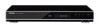
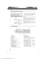
INTRODUCTION Identification of Controls Front panel 1 2 3 4* 5* 6* 7* (*) Notes: 1. These indicators are located in the sensor field. 2. When this unit is off, these indicators are dimmed. If a fin- ger is brought close to the sensor field, the indicators will be invoked and light up. 1. Disc tray 2. Remote sensor 3. Display • Refer to "Front Panel Display" on page 10. 4. OPEN/CLOSE indicator • When invoked (white), tap to open/close the disc tray. 5. STOP indicator • When invoked (white), tap to stop playback. 6. PLAY indicator • When invoked (white), tap to start playback. 8 7. ON/STANDBY indicator • When invoked (white), tap to turn on the unit, or to turn the unit into the standby mode. (To completely turn off the unit, you must unplug the AC power cord.) 8. SD card slot How to Power On Your Unit ? 1. Connect to a standard AC outlet to supply power to this unit, the ON/STANDBY indicator lights in red and then turns white at once. 2. After about 10 seconds, the ON/STANDBY indicator will turn red automatically. 3. Touch the ON/STANDBY button to turn on the unit. The ON/STANDBY indicator will remain white (ON mode). Rear panel 1 2 34 5 6 AC IN COMPONENT VIDEO OUTPUT Y PB PR SBL C SL FL LAN BITSTREAM / PCM USB HDMI OUT OPTICAL R L ANALOG AUDIO OUTPUT VIDEO OUTPUT SBR SW SR FR MULTI CHANNEL AUDIO OUTPUT 7 89 1. AC power cord • Connect to a standard AC outlet to supply power to this unit. • Unplug this cord from the AC outlet to completely turn off the unit. 2. LAN terminal • Use to connect a network equipment with LAN cable. 3. HDMI OUT jack • Use to connect a TV with an HDMI compatible port via an HDMI cable. 4. OPTICAL jack • Use to connect an AV receiver / amplifier, Dolby Digital / DTS decoder or other device with a digital audio optical input jack using a digital audio optical cable. 5. COMPONENT VIDEO OUT jacks • Use to connect a TV with component video inputs using a component video cable. 6. MULTI CHANNEL AUDIO OUTPUT jacks • Use to connect an AV receiver / amplifier with a audio cable. 7. USB jack • Use to connect USB flash drives (not included). 8. AUDIO OUT jacks • Use to connect a TV, an AV receiver / amplifier or other device with a composite audio cable. 9. VIDEO OUT jack • Use to connect a TV, an AV receiver or other device with a composite video cable. 7 Downloaded from www.Manualslib.com manuals search engine
-
 1
1 -
 2
2 -
 3
3 -
 4
4 -
 5
5 -
 6
6 -
 7
7 -
 8
8 -
 9
9 -
 10
10 -
 11
11 -
 12
12 -
13
-
14
-
15
-
16
-
17
-
18
-
19
-
20
-
21
-
22
-
23
-
24
-
25
-
26
-
27
-
28
-
29
-
30
-
31
-
32
-
33
-
34
-
35
-
36
-
37
-
38
-
39
-
40
-
41
-
42
-
43
-
44
-
45
-
46
-
47
-
48
-
49
-
50
-
51
-
52
-
53
-
54
-
55
-
56
-
57
-
58
-
59
-
60
-
61
-
62
-
63
-
64
 |
 |
