Toshiba MW30G71 Service Manual
Toshiba MW30G71 Manual
 |
View all Toshiba MW30G71 manuals
Add to My Manuals
Save this manual to your list of manuals |
Toshiba MW30G71 manual content summary:
- Toshiba MW30G71 | Service Manual - Page 1
FILE NO. 140-200519 (MFR'S VERSION A) SERVICE MANUAL COLOR TELEVISION/ VIDEO CASSETTE RECORDER/ DVD VIDEO PLAYER MW30G71 DOCUMENT CREATED IN JAPAN, July, 2005 - Toshiba MW30G71 | Service Manual - Page 2
A LASER SYSTEM. TO ENSURE PROPER USE OF THIS PRODUCT, PLEASE READ THIS SERVICE MANUAL CAREFULLY AND RETAIN FOR FUTURE REFERENCE. SHOULD THE UNIT REQUIRE MAINTENANCE, CONTACT AN AUTHORIZED SERVICE LOCATION-SEE SERVICE PROCEDURE. USE OF CONTROLS, ADJUSTMENTS OR THE PERFORMANCE OF PROCEDURES OTHER THAN - Toshiba MW30G71 | Service Manual - Page 3
when you order parts. (Particularly the VERSION LETTER.) 1. MODEL NUMBER and VERSION LETTER The MODEL NUMBER can be found on the back of each product and the VERSION LETTER can be found at the end of the SERIAL NUMBER. 2. PART NO. and DESCRIPTION You can find it in your SERVICE MANUAL. A1-2 - Toshiba MW30G71 | Service Manual - Page 4
as a bookcase or rack unless proper ventilation is provided or the manufacturer's instructions have been adhered to. 10. POWER SOURCES This unit should be operated only they may touch dangerous voltage points or short out parts that could result in fire or electric shock. Never spill or spray any - Toshiba MW30G71 | Service Manual - Page 5
Code, ANSI/NFPA 70, provides information with respect to proper grounding of the mast and supporting service. 20. REPLACEMENT PARTS When replacement parts are required, be sure the service technician uses replacement parts owner's manual of the other equipment carefully and follow the instructions 30. - Toshiba MW30G71 | Service Manual - Page 6
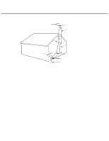
IMPORTANT SAFEGUARDS (CONTINUED) EXAMPLE OF ANTENNA GROUNDING AS PER THE NATIONAL ELECTRICAL CODE GROUND CLAMP ELECTRIC SERVICE EQUIPMENT NEC-NATIONAL ELECTRICAL CODE S2898A ANTENNA LEAD IN WIRE ANTENNA DISCHARGE UNIT (NEC SECTION 810-20) GROUNDING CONDUCTORS (NEC SECTION 810-21) GROUND CLAMPS - Toshiba MW30G71 | Service Manual - Page 7
the connection of Pick Up PCB and DVD PCB connector. NOTE • Before your operation, please read "PREPARATION OF SERVICING". • Use the Lead Free solder. • Manual soldering conditions • Soldering temperature: 320 ± 20˚C • Soldering time: Within 3 seconds • Soldering combination: Sn-3.0Ag-0.5Cu • When - Toshiba MW30G71 | Service Manual - Page 8
Side) Fig. 2 DISC REMOVAL METHOD AT NO POWER SUPPLY 1. Remove the Back Cabinet and TV/DVD/VCR Block. (Refer to item 1 of the DISASSEMBLY INSTRUCTIONS.) 2. Rotate the Main Gear in the direction of the arrow by hand. (Refer to Fig. 1) 3. Manually open the Tray. Main Gear DVD Deck Fig. 1 A1-7 - Toshiba MW30G71 | Service Manual - Page 9
on the front panel. 4. Simultaneously press and hold the '9' key on the remote control unit. 5. Hold both keys for more than 3 seconds. 6. Press the key on the front panel. 4. Simultaneously press and hold the '9' key on the remote control unit. 5. Hold both keys for more than 3 seconds. 6. The Tray - Toshiba MW30G71 | Service Manual - Page 10
melting point than standard solder; Typically the melting point is 50°F~70°F(30°C~40°C) higher. Please use a soldering iron with temperature control and products with the printed circuit board with PbF printing must be serviced with lead free solder. When soldering or unsoldering, completely remove - Toshiba MW30G71 | Service Manual - Page 11
LOCK ...ABOUT LEAD FREE SOLDER (PbF) ...TABLE OF CONTENTS ...GENERAL SPECIFICATIONS ...DISASSEMBLY INSTRUCTIONS 1. REMOVAL OF MECHANICAL PARTS AND P. C. BOARDS 2. REMOVAL OF VCR DECK PARTS 3. REMOVAL OF DVD DECK PARTS 4. REMOVAL OF ANODE CAP ...5. REMOVAL AND INSTALLATION OF FLAT PACKAGE IC KEY - Toshiba MW30G71 | Service Manual - Page 12
G-1 TV System G-2 VCR System G-3 DVD System G-4 Tuning System GENERAL SPECIFICATIONS Preset CH Stereo/Dual TV Sound Tuner Sound Muting System Destination CH Coverage Picture(FP) Sound(FS) FP-FS Actual 30 inch / 760mmV Flat (16:9) + 0.45 G NTSC 1080i/540p 2 Speaker Front 2.0 x 4.7 Inch 8 2.5W + - Toshiba MW30G71 | Service Manual - Page 13
GENERAL SPECIFICATIONS G-5 Signal Video Signal RGB Signal Audio Signal VCR DVD Hi-Fi Audio Signal G-6 Power Power Source Power Consumption Protector G-7 Regulation G-8 Temperature G-9 Operating Humidity Input Level Output Level S/N Ratio (Weighted) at DVD Mode S/N Ratio (Weighted) at - Toshiba MW30G71 | Service Manual - Page 14
Setup Yes Timer REC Set Yes Repeat Yes G-CODE(or SHOWVIEW or PLUSCODE)No. Entry Clock / Date No Yes TV/VCR Yes DVD Yes CH/AV(LINE) Yes Yes Manual Tracking Yes Picture Scroll Yes Play/Stop/FF/Rew/Rec/OTR/T-Rec/Pause/Eject/Tape In (Symbol Mark) Yes Auto Tracking/Manual Tracking - Toshiba MW30G71 | Service Manual - Page 15
Screen Size(4:3/16:9) OSD Display On/Off Picture Mode (Video/Film/Auto) JPEG Interval Audio DRC (Dynamic Range Control) Dialogue (On DRC[TV] / Off DRC[Std]) Surround System Disc/Card Slot Password Lock/ Un Lock Parental Select Files HDMI (480p/1080i/720p) Output Open Close No Disc - Toshiba MW30G71 | Service Manual - Page 16
Remote Control Unit GENERAL SPECIFICATIONS Unit Glow in Dark Remocon Remocon Format Format Custom Code Power Source Total Keys Keys Voltage(D.C) UM size x pcs TV CHCursor Right/Favorite CH+ Enter Picture Size Open/Close Eject RC-KH Yes TOSHIBA TOSHIBA 40-BFh,44-BBh,45-BAh 3V UM-4 x 2 pcs 50 Yes - Toshiba MW30G71 | Service Manual - Page 17
/VCR) Features (DVD) GENERAL SPECIFICATIONS Auto Head Cleaning VIDEO PLUS+(SHOWVIEW,G-CODE) Auto Clock Auto Setup Forward / Reverse Picture Search CH Program (Auto CH Memory) Surround Stable Sound Closed Caption TV Auto Shut off Function End Call Index Search SQPB CABLE CM Skip(30sec - Toshiba MW30G71 | Service Manual - Page 18
GENERAL SPECIFICATIONS Owner's Manual Language w/Guarantee Card Remote Control Unit -up Sheet Circuit Diagram Service Facility List Important Safeguard Sheet Input Select Main Power SW Indicator Power REC/OTR T-REC TV/VCR DVD Terminals Front Video Input Audio Input S Input 4 - Toshiba MW30G71 | Service Manual - Page 19
PCB Non-Halogen Demand Eyelet Demand Environmental standard requirement (by buyer) Pb-free No - - - - Double/White 916 x 691 x 733 Yes 1 Corner / 2 Edges / 4 Surfaces 40(ORION SPEC:25) 129 Sets PS 94V0 DECABROM PS 94V0 NON-DECABROM No Yes Green procurement of - Toshiba MW30G71 | Service Manual - Page 20
DISASSEMBLY INSTRUCTIONS 1. REMOVAL OF MECHANICAL PARTS AND P.C. BOARDS 1-1: BACK CABINET (Refer to Fig. 1-1) 1. Remove CRT PCB CP852 CP803 CP802B CP801 2 21 2 2 CP9604 Memory Card PCB Fig. 1-3 1-4: TV/DVD/VCR BLOCK (Refer to Fig. 1-4) 1. Remove the 2 screws 1. 2. Disconnect the following - Toshiba MW30G71 | Service Manual - Page 21
DISASSEMBLY INSTRUCTIONS 1-5: POWER PCB (Refer to Fig. 1-5) 1. Remove the screw 1. 2. Disconnect the following connectors: (CP1701 and CP1707). 3. Remove the POWER PCB in the direction of arrow. CP1707 1 Power PCB CP1701 TV/DVD/VCR Block 1-7: TOP SHIELD (Refer to Fig. 1-7) 1. Remove the 10 - Toshiba MW30G71 | Service Manual - Page 22
DISASSEMBLY INSTRUCTIONS 1-9: OPERATION PCB/DVD PCB/DVD DECK (Refer to Fig. 1-9) 1. Short circuit the Fig. 1-9 NOTE 1. Before your operation, please read "PREPARATION OF SERVICING". 2. Use the Lead Free solder. 3. Manual soldering conditions • Soldering temperature: 320 ± 20˚C • Soldering time: - Toshiba MW30G71 | Service Manual - Page 23
DISASSEMBLY INSTRUCTIONS 1-12: VCR PCB (Refer to Fig. 1-12) 1. Remove the screw 1. 2. Remove the screw 2. 3. Remove the 7 screws 3. 4. Remove the AV Jack Shield. 5. Remove the VCR PCB in the direction of arrow. 3 3 AV Jack Shield VCR PCB 1 3 3 3 33 2 Bottom Plate Fig. 1-12 B1-4 - Toshiba MW30G71 | Service Manual - Page 24
DISASSEMBLY INSTRUCTIONS 2. REMOVAL OF VCR DECK PARTS 2-1: TOP BRACKET (Refer to Fig. 2-1) 1. Extend the 2 supports 1. 2. Slide the 2 supports 2 and remove the Top Bracket. NOTE 1. After the installation of the Top Bracket, bend the support 1 so that the Top Bracket is fixed. Top Bracket 1 1 - Toshiba MW30G71 | Service Manual - Page 25
DISASSEMBLY INSTRUCTIONS 2-5: LOADING MOTOR/WORM (Refer to Fig. 2-5-A) 1. Remove the screw 1. Remove the Tension Spring. 3. Unlock the 2 supports 1 and remove the Tension Band. 4. Unlock the support 2 and remove the Tension Arm Ass'y. 5. Unlock the support 3 and remove the Tension Connect. 6. Float - Toshiba MW30G71 | Service Manual - Page 26
Connect DISASSEMBLY INSTRUCTIONS Tension Band clockwise and bend the hook section to remove it. 3. Unlock the 2 supports 1 and remove the T Brake Band. T Brake Band Idler Gear S the S Reel and T Reel installation, check if the correct parts are installed. (Refer to Fig. 2-8-B) 2. In case - Toshiba MW30G71 | Service Manual - Page 27
DISASSEMBLY INSTRUCTIONS 2-9: CASSETTE OPENER/PINCH ROLLER BLOCK/P5 ARM ASS'Y (Refer to Fig. 2-9-A) 1. Unlock the support 1 and remove the 2-11 2-12: CYLINDER UNIT ASS'Y (Refer to Fig. 2-12) 1. Unlock the support 1 and remove the AHC Ass'y. 2. Disconnect the following connector: (CD2001). 3. Remove - Toshiba MW30G71 | Service Manual - Page 28
DISASSEMBLY INSTRUCTIONS 2-13: CAPSTAN DD UNIT (Refer to Fig. 2-13) 1. Remove the Capstan Belt. 2. Remove the screw 1. 3. Remove the Capstan Holder. 4. Remove the 3 screws 2. 5. Remove the Capstan - Toshiba MW30G71 | Service Manual - Page 29
/LED REFLECTOR (Refer to Fig. 2-17-A) 1. Remove the P4 Cap. 2. Unlock the support 1 and remove the Cassette Guide Post. 3. Remove the Inclined Base S/T Unit. 4. Remove the screw 2. 5. Remove the LED Reflector. Cassette Guide Post 1 Loading Arm T Unit Loading Arm S Unit Fig. 2-15-B Inclined Base - Toshiba MW30G71 | Service Manual - Page 30
DISASSEMBLY INSTRUCTIONS 3. REMOVAL OF DVD DECK PARTS NOTE 1. Disassemble only the DVD DECK PARTS parts listed here. Minute adjustments are needed if the disassembly is done. If the repair is needed except listed parts, replace the DVD MECHA ASS'Y. 3-1: TRAY (Refer to Fig. 3-1-A) 1. Set the Tray - Toshiba MW30G71 | Service Manual - Page 31
DISASSEMBLY INSTRUCTIONS 3-3: LOADING MOTOR PCB ASS'Y/ LOADING BELT (Refer to Fig. 3-3-A) 1. Remove the Loading to Fig. 3-4-A) 1. Press down the catcher 1 and slide the Rack Loading. 2. Unlock the support 2 and remove the Pulley Gear. 3. Remove the Main Gear. Pulley Gear Main Gear Rack Loading - Toshiba MW30G71 | Service Manual - Page 32
DISASSEMBLY INSTRUCTIONS NOTE 1. In case of the Clamper Ass'y installation, install correctly as Fig. 3-5-B. Clamper Plate Clamper No gap 3-7: SWITCH PCB ASS'Y/MIDDLE GEAR/FEED MOTOR (Refer to Fig. 3-7-A) 1. Remove the screw 1. 2. Remove the Switch PCB Ass'y. 3. Unlock the support 2. 4. Remove - Toshiba MW30G71 | Service Manual - Page 33
DISASSEMBLY INSTRUCTIONS Main Chassis Ass'y (Bottom Side) Check Hook Check Hook Check Hook Check Hook • Loosen the wire in the direction of the arrow. Fig. 3-7-D 3-8: FFC WIRE - Toshiba MW30G71 | Service Manual - Page 34
DISASSEMBLY INSTRUCTIONS 4. REMOVAL OF ANODE CAP Read the following NOTED items before end of an Alligator Clip to the metal part of a flat-blade screwdriver and the other end to ground. While holding the plastic part of the insulated Screwdriver, touch the support of the Anode with the tip of the - Toshiba MW30G71 | Service Manual - Page 35
DISASSEMBLY INSTRUCTIONS 5. REMOVAL AND INSTALLATION OF FLAT PACKAGE IC REMOVAL 1. Put Masking Tape (cotton tape) around the Flat Package IC to protect other parts from any damage. (Refer to Fig. 5-1.) NOTE Masking is carried out on all the parts located within 10 mm distance from IC leads. IC - Toshiba MW30G71 | Service Manual - Page 36
DISASSEMBLY INSTRUCTIONS INSTALLATION 1. Take care of the polarity of new IC and a magnifying glass. Confirm that no abnormality is found on the soldering position and installation position of the parts around the IC. If some abnormality is found, correct by resoldering. NOTE When the IC leads are - Toshiba MW30G71 | Service Manual - Page 37
Recording : Recording-Chrominance : Recording-Luminance : Reel Brake : Reel Sensor : Reference : Regulated, Regulator : Rewind : Reverse : Radio Frequency : Remote Control : Relay : Serial Clock : Sensor Common : Serial Data : Segment : Select, Selector : Sensor : Search Mode : Serial Input : Sound - Toshiba MW30G71 | Service Manual - Page 38
S STB SW SYNC SYNC SEP T TR TRAC TRICK PB TP U UNREG VV VCO VIF VP V.PB VR V.REC VSF VSR VSS V-SYNC VT X X'TAL Y Y/C KEY TO ABBREVIATIONS : Serial Strobe : Switch : Synchronization : Sync Separator, Separation : Transistor : Tracking : Trick Playback : Test Point : Unregulated : Volt : Voltage - Toshiba MW30G71 | Service Manual - Page 39
to the SERVICE MODE function, press and hold both buttons simultaneously on the main unit or on the main unit and on the remote control for Adjust the PG SHIFTER manually. Refer to the "ELECTRICAL ADJUSTMENT" (PG SHIFTER). 2 Adjusting of the Tracking to the center position. TV mode VOL. (-) MIN - Toshiba MW30G71 | Service Manual - Page 40
Guide Post Cylinder Unit 500 hours 1,000 hours 1,500 hours 2,000 hours 2,500 hours Notes Clean those parts in contact with the tape. Clean the rubber, and parts the TV mode. 2. Set the VOLUME to minimum. 3. Press both VOL. DOWN button on the set and Channel button (6) on the remote control - Toshiba MW30G71 | Service Manual - Page 41
PREVENTIVE CHECKS AND SERVICE INTERVALS CLEANING NOTE After cleaning the heads with isopropyl alcohol, do not run a tape until the heads dry completely. If the heads are not completely - Toshiba MW30G71 | Service Manual - Page 42
If a service repair is undertaken where it has been required to change the MEMORY IC, the following steps should be taken to ensure correct data settings while making reference to TABLE 1 and 2. TV side 64 0020 68 00 A0 00 00 00 00 00 88 02 00 54 98 30 04 76 0030 77 05 07 21 10 03 00 22 75 D1 03 - Toshiba MW30G71 | Service Manual - Page 43
00 00 00 00 00 0820 35 90 18 F0 07 14 35 80 80 80 7E 63 7E 6B 66 B5 0830 30 0B 0F 02 01 00 00 01 00 00 00 00 00 00 00 00 0840 67 10 88 B0 05 1D B0 58 02 20 08 80 C5 14 28 64 08 70 1090 C0 73 07 04 5D 10 58 38 12 18 06 30 30 08 0E 14 10A0 E2 B3 06 EA 01 94 02 03 16 03 18 1A 1D 46 01 79 10B0 02 20 - Toshiba MW30G71 | Service Manual - Page 44
00 00 02 4C 04 32 F8 01 94 00 73 03 85 00 8E 4C 04 36 04 12 00 2E 02 30 F4 03 30 02 33 02 63 04 65 33 02 63 04 65 04 2C 00 32 98 08 20 04 12 00 2E 02 30 6C 08 98 08 20 04 30 02 32 0D 08 80 35 CC C7 01 00 00 01 00 00 00 00 00 00 00 00 02 - Toshiba MW30G71 | Service Manual - Page 45
01 58 02 20 08 80 C5 14 28 64 08 70 1490 C0 73 07 04 5D 10 58 38 12 18 06 30 30 08 0E 14 14A0 E2 B3 06 EA 01 94 02 03 16 03 18 1A 1D 46 01 79 14B0 02 1E 00 00 00 00 00 00 00 00 08 88 88 08 80 06 F0 14E0 00 28 00 05 06 EA 01 30 02 0B 02 11 02 24 BF 0D 14F0 0D 02 01 00 00 72 DF 06 5A 03 0D 02 0D 02 - Toshiba MW30G71 | Service Manual - Page 46
01 58 02 20 08 80 C5 14 28 64 08 70 1640 C0 73 07 04 5D 10 58 38 12 18 06 30 30 08 0E 14 1650 E2 B3 06 EA 01 94 02 03 16 03 18 1A 1D 46 01 79 1660 02 20 00 00 00 00 00 00 00 00 08 88 88 08 80 06 F0 1690 00 28 00 05 06 EA 01 30 02 0B 02 11 02 24 BF 0D 16A0 0D 02 01 00 00 73 DF 06 AD 01 1A 04 1A 04 - Toshiba MW30G71 | Service Manual - Page 47
01 58 02 20 08 80 C5 14 28 64 08 70 17F0 C0 73 07 04 5D 10 58 38 12 18 06 30 30 08 0E 14 1800 E2 B3 06 EA 01 94 02 03 16 03 18 1A 1D 46 01 79 1810 02 20 00 00 00 00 00 00 00 00 08 88 88 08 80 06 F0 1840 00 28 00 05 06 EA 01 30 02 0B 02 11 02 24 BF 0D 1850 0D 02 01 00 00 70 DF 06 60 03 09 02 08 02 - Toshiba MW30G71 | Service Manual - Page 48
01 58 02 20 08 80 C5 14 28 64 08 70 19A0 C0 73 07 04 5D 10 58 38 12 18 06 30 30 08 0E 14 19B0 E2 B3 06 EA 01 94 02 03 16 03 18 1A 1D 46 01 79 19C0 02 1A 00 00 00 00 00 00 00 00 08 88 88 08 80 06 F0 19F0 00 28 00 05 06 EA 01 30 02 0B 02 11 02 24 BF 0D 1A00 0D 02 01 00 00 70 DF 06 60 03 09 02 08 02 - Toshiba MW30G71 | Service Manual - Page 49
10 01 38 00 38 00 6C 00 6C 00 00 F7 EF 07 00 1B10 6E 00 4D 03 23 00 05 02 30 58 01 04 00 E2 02 D9 1B20 00 46 01 AA 02 C7 01 50 05 DE 02 E0 01 B1 03 69 10 01 38 00 38 00 6C 00 6C 00 01 F7 EF C7 00 1B60 6E 00 4D 03 23 00 05 02 30 58 01 04 00 E2 02 E5 1B70 00 29 01 AA 02 C7 01 2C 06 DE 02 E0 01 B1 03 69 - Toshiba MW30G71 | Service Manual - Page 50
WHEN REPLACING EEPROM (MEMORY) IC INI +0 +1 +2 +3 +4 +5 +6 +7 +8 +9 +A +B +C +D +E +F 1D00 00 0E 01 AA 02 C7 01 8E 03 DF 02 E0 01 B1 03 69 1D10 00 03 00 00 61 FE 05 F5 00 00 08 3F 00 BF 07 00 1D20 00 C0 03 C0 03 00 00 EF 02 EF 02 E0 01 29 03 60 1D30 00 95 00 1C 00 1C 00 54 00 54 00 01 35 EC 07 00 - Toshiba MW30G71 | Service Manual - Page 51
is now selected and should "blink". Using the UP/DOWN button on the remote, step through the ADDRESS until required ADDRESS to be changed is reached. CRT POWER, and set to the TV mode. 11. Press both VOL. DOWN button on the set and Channel button (1) on the remote control for more than 2 seconds - Toshiba MW30G71 | Service Manual - Page 52
, Press both VOL. DOWN button on the set and Channel button (7) on the remote control for more than 2 seconds. ADDRESS and DATA should appear as FIG 2. 5. POWER, and set to the TV mode. 12. Press both VOL. DOWN button on the set and Channel button (1) on the remote control for more than 2 seconds - Toshiba MW30G71 | Service Manual - Page 53
test point of SERVICE and GROUND Confirmation of Tape Tension on Playback PREPARATION FOR SERVICING How to use the Servicing Fixture 1. Remove the TV/DVD/VCR Block from the set. Be sure to place the parts on a tape. Turn on the power and re-check the cable before checking the trouble points. D1-1 - Toshiba MW30G71 | Service Manual - Page 54
. 3. Confirm that the left meter of the torque tape indicates 25~40gf•cm during playback in SP mode. Tentelometer (JG185) Video Tape D2-1 P1 Post Guide Roller Fig. 1-3 - Toshiba MW30G71 | Service Manual - Page 55
Turn the Torque Gauge (JG002E) counterclockwise. 4. Then, confirm that it indicates 30~50gf•cm. The position at FF mode. Pinch Roller Block Stop at this the parts of the tape running mechanism because of long term usage or failure, the confirmation and adjustment are necessary. 2-1: GUIDE ROLLER - Toshiba MW30G71 | Service Manual - Page 56
the position of the Tension Post. (Refer to item 1-2) 3. Adjust the Guide Roller. (Refer to item 2-1) 4. Confirm and adjust the Audio/Control Head the VHS Alignment Tape. 7. Press and hold the Digital Tracking button on the remote control more than 2 seconds to set tracking to center. 8. Set the X - Toshiba MW30G71 | Service Manual - Page 57
MECHANICAL ADJUSTMENTS 3. MECHANISM ADJUSTMENT PARTS LOCATION GUIDE 4 5 6 3 2 7 1 10 9 8 1. Tension Connect 2. Tension Arm 3. Guide Roller 4. Audio/Control Head 5. X value adjustment driver hole 6. P4 Post 7. T Brake Spring 8. T Reel 9. S Reel 10. Adjusting section for the Tension Arm - Toshiba MW30G71 | Service Manual - Page 58
parts or PCB assemblies. CAUTION • Use an isolation transformer when performing any service R/G.DRV 28 B/R.DRV 29 R.BIAS(C) 30 G.BIAS(C) 31 B.BIAS(C) 32 R/G.DRV(C) remote control to end the adjustments. 5. To display the adjustment screen for AV, CS and HD-MI mode, press the TV/VIDEO button on the remote - Toshiba MW30G71 | Service Manual - Page 59
. 2. Place the set in AV MODE without signal. 3. Using the remote control, set the brightness and contrast to normal position. 4. Activate the screen becomes clearest. Then adjust the F2 VR. Focus VR F1 VR F2 VR TV FULL 00 OSD H 1 A B Fig. 2-3 2-6: HORIZONTAL POSITION/ HORIZONTAL SIZE - Toshiba MW30G71 | Service Manual - Page 60
select "SUB CONT". 7. Check if the step No. SUB CONT is "16". 8. Receive a broadcast and check if the picture is normal. 9. Press the TV/VIDEO button on the remote control to set to the CS mode. 10. Activate the adjustment mode display of Fig. 1-1 and press the channel button (52) on the - Toshiba MW30G71 | Service Manual - Page 61
of TP806 is straight line. If is not a straight line, adjust to TINT again. 9. Receive the color bar pattern. (Audio Video Input) 10. Press the TV/VIDEO button on the remote control to set to the AV mode. Then perform the above adjustments 2~8. 11. Receive the color bar pattern. 12. Press the - Toshiba MW30G71 | Service Manual - Page 62
referring below. "A" Fig. 2-4 100% 120% Fig. 2-5 2-17: TINT 1. Press the TV/VIDEO button on the remote control to set to the DVD mode. 2. Connect the oscilloscope to TP806. 3. Activate the 00 00 00 00 00 00 00 00 00 00 02 02 02 02 02 30 30 30 30 30 16 16 16 16 16 21 21 21 21 21 128 128 128 128 128 - Toshiba MW30G71 | Service Manual - Page 63
3-3: STATIC CONVERGENCE NOTE NOTE Adjust after performing adjustments in section 3-2. 1. Turn the unit on and let it warm up for at least 30 minutes before performing the following adjustments. 2. Place the CRT surface facing east or west to reduce the terrestrial magnetism. 3. Turn ON the - Toshiba MW30G71 | Service Manual - Page 64
ELECTRICAL ADJUSTMENTS 4. ELECTRICAL ADJUSTMENT PARTS LOCATION GUIDE (WIRING CONNECTION) VM COIL PCB CP853 S853 S854 CD852 CRT PCB R841 TP806 CP852 CP804 TP805 R834 J801 CP803 CRT TP804 R801 CP808B CP851B CP801 - Toshiba MW30G71 | Service Manual - Page 65
9V IC4003 BA33E00WHFP VIDEO BUFFER Q8102~Q8104 ASDATA0 AMCLK ABCLK ALRCLK STEREO DAC IC8502 PCM1753DBQR DVD AUDIO R DVD AUDIO L E-1 FROM/TO TV BLOCK CD4002 CU2B2201 GND(D) 1 GND(D) 2 TX 3 RX 4 GND(M) 5 P.CON+9V 6 P.CON+A5V 7 UNREG+3.8V 8 UNREG+3.8V 9 GND(A) 10 SPDIF 11 CP8101_3 - Toshiba MW30G71 | Service Manual - Page 66
18 VCC 19 VCC 20 CD/DAT3 21 CMD 22 VSS 23 VDD 24 CLK 25 VSS 26 DAT0 27 DAT1 28 DAT2 29 VSS 30 BS 31 VCC 32 SDI0 33 RESERVED 34 INS 35 RESERVED 36 SCLK 37 VCC 38 VSS 39 SD#CD 40 SD#COM 41 SD - Toshiba MW30G71 | Service Manual - Page 67
INS. COMP 60 OUT 24 SYNC SEP 6dB 26 11 5 4 3 2 10 80 78 76 32 31 30 COIL, BIAS OSC L4502 Q4505 5 2 BIAS CTL Q4508 BUFFER 6 3 Q4504 BIAS OSC 4 1 L4507 2 C_AUDIO FSC DVD_VIDEO AV/SENC COUNT/ CONNECTOR TV HI-FI/ DEMODULATOR DVD IN/OUT V.REC_ST_H CTL+ CTL- SERVO MICON E-6 - Toshiba MW30G71 | Service Manual - Page 68
MICON VCR_POWER_H SYSCON/TIMER/SERVO IC IC1001 OEC7122A CV OUT 52 REGULATOR VCR_POWER_H TV VCR_POWER_FAIL AT 5.6V REGULATOR BOT SENSOR Q1001 CAPSTAN DD UNIT CP3001 11 CYL FG/PG HI-FI/ DEMODULATOR Y/C/AUDIO/ HEAD AMP SCL1 SDA1 BUS_OFF VCR_CS VCR_CLK VCR_DA_IN VCR_DA_OUT TV MICON E-8 - Toshiba MW30G71 | Service Manual - Page 69
+3.3V 5 UNREG+13V 7 UNREG+5V 8 UNREG+5V 9 AT+5.6V 14 TUNER 32V TV +B SERVO MICON MOTOR+12V Q3007 P.CON+12V SW Q3013 AT 3.3V SW REGULATOR BLOCK Q3005 P.CON+ 5V_VCR SW Q3010 P.CON+5V SW E-9 AT+3.3V CHROMA_POWER_H TV MICON DVD_H VCR_POWER_H SERVO MICON P.CON+12V P.CON+9V_VCR P.CON+5V P.CON - Toshiba MW30G71 | Service Manual - Page 70
E-11 IN/OUT BLOCK DIAGRAM KEY_A KEY_B KEY_C TV MICON REMOCON_IN TV_POWER_H T-REC_LED REC_LED POWER DVD SKIP FF DVD PLAY CH.DOWN CH.UP REC/OTR FF PLAY STOP/EJECT REW DVD STOP DVD - Toshiba MW30G71 | Service Manual - Page 71
TV SOUND +B TV_POWER_H TV MICON TV_A_MUTE SCL SDA REGULATOR P.CON+9V SOUND AMP/SURROUND BLOCK DIAGRAM SOUND AMP IC IC351 AN7522N 1 5968 2 12 4 10 18 17 16 19 SURROUND-IC IC301 AN5891SA-E1V 31 30 3 SPEAKER SP352 SPEAKER SP351 AUDIO_OUT_L AUDIO_OUT_R HI-FI/ DEMODULATOR E-13 E-14 - Toshiba MW30G71 | Service Manual - Page 72
AV/ SENC COUNT/ CONNECTOR DVD IN/OUT Y/C/AUDIO/CCD /HEAD AMP DVI_A_L DVI_A_R DVD_AUDIO_R DVD_AUDIO_L HF1 HF2 HF_COM SERVO MICON ST_SELECT Y/C/AUDIO/CCD /HEAD AMP FSC Y/C_AUDIO NORMAL_A_IN E-15 Hi-Fi/DEMODULATOR BLOCK DIAGRM HIFI AUDIO/H.AMP/DEM IC IC5501 LA72670BM 11 73 74 AGC 12 L/R - Toshiba MW30G71 | Service Manual - Page 73
SDA CP4203 11 V_AV 10 C(CVBS) 6 Y(1) 3 Pb(1) 1 Pr(1) TV MICON HI-FI/ DEMODULATOR SDA SCL SWD_A_IN_R SWD_A_IN_L SIF REGULATOR P.CON+3.3V 1 Q4203 D AUDIO DRIVER Y_OUT D_SYNC1_IN Cr_IN Cb_IN SYNC_COUNT IC705 TA1383FG 29 28 30 Cb_OUT Cr_OUT 22 23 24 Y SW IC IC707 NJM2533V 3 IN2 IN1 1 - Toshiba MW30G71 | Service Manual - Page 74
REGULATOR IC1704 KIA7805API 1 3 Q1702 HDMI+4V OUT AV/ SENC COUNT/ CONNECTOR TV MICON Y_OUT Pb_OUT Pr_OUT OSD_R OSD_G OSD_B SDA SCL REGULATOR P.CON+9V E-19 39 ANALOG OSD R IN 38 ANALOG OSD G IN 37 ANALOG OSD B IN 31 SDA 30 SCL 19 DEF/DAC Vcc 55 Y/C Vcc R OUT 43 G OUT 42 B OUT 41 - Toshiba MW30G71 | Service Manual - Page 75
EEP_DATA CP103 2 SCL_EEP 3 SDA_EEP 6 SDA 5 SCL TV MICON BLOCK DIAGRAM SYSTEM RESET IC102 PST3229NR OUT 1 IN 2 D101 EEP ROM IC 64K IC199 31 SCL2 28 VCC(5V) 99 VCC(3.3V) 16 OSD_R 32 OSD_G 33 OSD_B 34 TV POWER 81 AUDIO MUTE 51 SCL SDA SDA2 SCL2 AT+5.6V AT+3.3V OSD_R OSD_G OSD_B TV_POWER_H - Toshiba MW30G71 | Service Manual - Page 76
DVD IN/OUT BLOCK DIAGRAM MIXER IC IC8004 NJM4580M (TE1) 5 7 3 1 E-23 DVD_RESET TX RX P.CON+9V_DH P.CON+5V_D P.CON+3.8V ZERO SPDIF-134 TV MICON REGULATOR SOUND AMP/ SURROUND AV/SYNC COUNT/ CONNECTOR DVD_AUDIO_R DVD_AUDIO_L HI-FI/ DEMODULATOR DVD_Y DVD_C DVD_VIDEO AV/SYNC COUNT/ CONNECTOR - Toshiba MW30G71 | Service Manual - Page 77
RX087 RX0+ 91 RX192 RX1+ 96 RX297 RX2+ 81 EXT_RES 82 AVCC 89 AVCC 93 AVCC 95 AVCC VSYNC 34 SCK 32 WS 31 SD0 30 MCLK 27 VCC 100 OVCC 67 VCC 64 OVCC 56 OVCC 47 VCC 40 PVCC2 23 OVCC 21 VCC 17 CSCL 74 CSDA 75 RXT - Toshiba MW30G71 | Service Manual - Page 78
RXT_RST# H_INT +5V CSDA INTERFACE CSCL SDO SCK WS MCLK +12V Q3606 BUFFER EEP ROM IC IC3608 BR24L32F-WE2 VCC 8 1 A0 WP 7 2 A1 SCL 6 3 A2 SDA 5 4 GND Q3605 BUFFER AUDIO_DAC IC IC3607 CS4334-KSZER 1 SDATA AOUT L 8 2 SCLK VA 7 3 LRCLK GND 6 4 MCLK AOUTR 5 MICON2 BLOCK DIAGRAM HDMI MICON IC - Toshiba MW30G71 | Service Manual - Page 79
24) 78 SDRAM DATA(25) 79 SDRAM DATA(26) 82 SDRAM DATA(27) 83 SDRAM DATA(28) 84 SDRAM DATA(29) 85 SDRAM DATA(30) 86 SDRAM DATA(31) 87 ANALOG U 170 ANALOG V 176 ANALOG Y 173 SDRAM IC3902 MT48LC2M32B2P-6(Y14W) 2 DQ0 4 DQ1 5 DQ2 7 DQ3 45 DQ24 47 DQ25 48 DQ26 50 DQ27 51 DQ28 53 DQ29 54 DQ30 56 DQ31 E-30 - Toshiba MW30G71 | Service Manual - Page 80
PRINTED CIRCUIT BOARDS DVD (TOP SIDE) DVD ( BOTTOM SIDE) B2601 B4010 C4057 C2648 D2602 C2634 B2602 C2657 DME028A C4060 C2312 R2617 W848 C2307 Q2602 R2335 R2322 R2634 R2615 R2636 R2616 R2618 C2609 C2626 C2631 C2630 R2626 R2309 R2314 R2310 C2304 R2313 R2315 Q2601 C2617 C2615 - Toshiba MW30G71 | Service Manual - Page 81
C442 C441 D406 C426 L408 C406 L407 C417_1 C418 D405 HS403 FB401 W808 D412 C436 W827 D415 W814 C434 CAUTION C445 R452 ATTENTION INFORMATION POUR SERVICE DES PIECE CRITIQUE , VOIR AU VERSO. R438 W823 C437 D411 FOR - Toshiba MW30G71 | Service Manual - Page 82
C5537 R5502 W300 C5503 W276 C5542 W428 R359 R353 W181 W179 W180 CP4503 W292 W291 W229 R4517 L4505 W274 CP303 PRINTED CIRCUIT BOARDS VCR (INSERTED PARTS) CD3003 SOLDER SIDE W382 W240 W244 W236 W281 L4506 W298 Q1002 W254 R4563 W874 R4518 W256 W224 W221 W218 W216 W214 W261 W226 W225 - Toshiba MW30G71 | Service Manual - Page 83
C4227 C4236 R006 C008 R312 R302 Q350 C002 R001 R002 R004 R005 C006 C320 C324 C313 C332 PRINTED CIRCUIT BOARDS VCR (CHIP MOUNTED PARTS) SOLDER SIDE R1002 R8021 R8023 R8025 R8020 Q3012 Q3006 R8047 R8027 C8017 R3007 R3009 Q3001 C8025 C8090 IC8004 R8056 R8051 R8026 R8054 C8077 - Toshiba MW30G71 | Service Manual - Page 84
F-9 HS3601 Q3607 Q3603 R3678 HD-MI (TOP SIDE) NR3909 NR3911NR3910 NR3908 NR3907 NR3904NR3903NR3902 Q3902 Q3901 Q3906 Q3905 R3926 C3912 L3903 R3914 R3936 R3928 W820 L3909 C3949C3966 L1514 C1567 W833 C3971 C1565 C1541 C1502 C1557 C1552 R3922 R3921 W836 C1540_1 81 1 C1501 C1551 C1507 - Toshiba MW30G71 | Service Manual - Page 85
F-11 PRINTED CIRCUIT BOARDS POWER SOLDER SIDE W809 C1733 L1703 R1709 R1701 CP1710 W014 L1701 CP1707 R1732 W812 R1713 R1702 W011 C1732 C1730 R1730 Q1704 L1702 C1725 CEE024A C1724 R1715 C1729 Q1702 W013 R1729 HS1702 C1727 W015 C1728 R1728 IC1705 R1724 R1727 IC1704 W007 - Toshiba MW30G71 | Service Manual - Page 86
R9640 R9610 R9603 B9601 C9605 C9604 MEMORY CARD ( BOTTOM SIDE) DED022A R9639 R9636 R9638 R9601 R9611 R9612 R9609 R9608 R9652 SW1 LOADING MOTOR (INSERTED PARTS) SOLDER SIDE LOADING MOTOR (CHIP MOUNTED PARTS) SOLDER SIDE SW SOLDER SIDE BL GR OR YE SW2 CD2301 M2602 M2601 F-13 CD2302 F-14 - Toshiba MW30G71 | Service Manual - Page 87
VNB DVDPD CDLD DVDLD CD_E VPB CD_F VC 17 18 19 20 21 22 23 24 25 26 27 28 29 30 31 32 2.6 2.6 5.1 5.1 3.7 5.1 0.2 0.2 0 3.3 0 2.7 2.2 2.3 2.9 0.2 33 34 35 SUBJECT TO CHANGE WITHOUT NOTICE NOTE:THE DC VOLTAGE EACH PART WAS MEASURED WITH THE DIGITAL TESTER DURING PLAYBACK. A B C G-1 D E - Toshiba MW30G71 | Service Manual - Page 88
0.4 3.3 0 0 0 3.1 3.1 3.2 0 3.3 3.3 52 51 50 49 48 47 46 45 44 43 42 41 40 39 38 37 36 35 34 33 32 31 30 29 28 27 26 25 24 23 22 21 20 19 18 17 16 15 14 13 12 11 10 9 8 7 6 5 4 3 2 1 208 207 206 205 CON+3.3V GND 1 NOTE:THE DC VOLTAGE EACH PART WAS MEASURED WITH THE DIGITAL TESTER NOTE: THIS - Toshiba MW30G71 | Service Manual - Page 89
24 23 22 21 20 19 18 17 16 15 14 13 12 11 10 9 25 26 27 28 29 30 31 32 33 34 35 36 37 38 39 40 41 42 43 44 45 46 47 48 3.3 VCCQ SD_A2 C4047 SD_A3 0.1 F C4044_1 6.3V 220 KA NOTE:THE DC VOLTAGE EACH PART WAS MEASURED WITH THE DIGITAL TESTER DURING PLAYBACK. E NOTE: THIS SCHEMATIC DIAGRAM IS - Toshiba MW30G71 | Service Manual - Page 90
HA0 17 HD0 18 HD1 19 HD2 20 SW WP 21 FCUIF34 22 FCUIF37 23 CARD_DETECT 24 H 8 7 6 5 4 3 2 1 A B C G-7 2 NOTE:THE DC VOLTAGE EACH PART WAS MEASURED WITH THE DIGITAL TESTER DURING PLAYBACK. D E NOTE: THIS SCHEMATIC DIAGRAM IS THE LATEST AT THE TIME OF PRINTING AND SUBJECT TO - Toshiba MW30G71 | Service Manual - Page 91
JG037 JG042 JG040 JG038 C8122 0.001 B C8121 16V 10 MH7 ZERO I2CDATA/MD I2CCLK/MC ML AMCLK ABCLK ASDATA0 ALRCLK 1 NOTE:THE DC VOLTAGE EACH PART WAS MEASURED WITH THE DIGITAL TESTER NOTE: THIS SCHEMATIC DIAGRAM IS THE LATEST AT THE TIME OF PRINTING AND SUBJECT TO CHANGE WITHOUT NOTICE DURING - Toshiba MW30G71 | Service Manual - Page 92
CLK 25 SD VSS 26 DAT0 27 DAT1 28 DAT2 29 VSS 30 BS 31 VCC 32 SDI0 33 RESERVED 34 MS INS 35 OF PRINTING AND SUBJECT TO CHANGE WITHOUT NOTICE NOTE:THE DC VOLTAGE EACH PART WAS MEASURED WITH THE DIGITAL TESTER DURING PLAYBACK. CAUTION: DIGITAL TRANSISTOR PCBDM0 1 DED022 B - Toshiba MW30G71 | Service Manual - Page 93
2.6 4.0 3.3 3.3 2.3 NC 5.0 5.0 0.1 B 0 2.2 0.8 4.7K 21 22 23 24 25 26 27 28 29 30 31 32 33 34 35 36 37 38 39 40 R4513 820 80 79 78 77 76 75 74 73 72 71 70 69 DIAGRAM IS THE LATEST AT THE TIME NOTE:THE DC VOLTAGE EACH PART WAS OF PRINTING AND SUBJECT TO CHANGE WITHOUT NOTICE MEASURED WITH THE - Toshiba MW30G71 | Service Manual - Page 94
PART WAS MEASURED WITH THE DIGITAL TESTER DURING PLAYBACK. A B R1014 100 1/4W R1021 100 1/4W 33K 4.7K C1030 C1032 0.0033 B SERVICE 9 10 11 12 13 14 15 16 17 18 19 20 21 22 23 24 25 26 27 28 29 30 0 0 0 0 0 0.2 NC NC NC NC 0 0 NC5.1 5.1 5.0 2.5 2.5 5.0 5.0 0 FROM/TO TV MICON VCR_CS VCR_CLK - Toshiba MW30G71 | Service Manual - Page 95
5 UNREG+13V 7 6 MOTOR GND 7 UNREG+5V 8 UNREG+5V 9 AT+5.6V 10 TV POWER H 11 GND 12 GND 13 P.FAIL 14 TUNER+32V L3003 15 DEGAUSS H W5T29X7.5X19 R3016 VCR_POWER_H 10K P.CON+12V DVD_AUDIO_R NOTE:THE DC VOLTAGE EACH PART WAS MEASURED WITH THE DIGITAL TESTER DURING PLAYBACK. D NOTE: - Toshiba MW30G71 | Service Manual - Page 96
/TO REGULATOR GND 5 FROM/TO SYSCON/SERVO/TIMER AT+5V FROM/TO TV MICON TV_POWER_H KEY_C 4 KEY_B KEY_A REMOCON_IN REC_LED T-REC_LED 3 2 1 R2206 560 6 KEY_A 5 KEY_B 4 3 NOTE:THE DC VOLTAGE EACH PART WAS MEASURED WITH THE DIGITAL TESTER DURING PLAYBACK. NOTE: THIS SCHEMATIC DIAGRAM - Toshiba MW30G71 | Service Manual - Page 97
GND ZERO P.CON+5V P.CON+9V 5 FROM/TO TV MICON TV_POWER_H TV_A_MUTE AV5 SDA SCL 4 3 FROM/ AGC + SURR Tone Control Volume 2.2K Control MODE control VCC R IN Vref 32 31 30 29 2.5 7.8 4.6 3.9 NC 28 0 NC NC BB RB RT BLD TD 27 26 C NOTE:THE DC VOLTAGE EACH PART WAS MEASURED WITH THE DIGITAL TESTER - Toshiba MW30G71 | Service Manual - Page 98
HIFI H.SW 21 22 23 24 25 26 27 28 29 30 31 32 33 34 35 36 37 38 39 40 80 4.8 C5564 0.1 F 0.4 DEC DEMOD DEMOD DEV 0 FROM/TO TV MICON 16V 22 KA C5516 0.7 ST/SAP SW CONT SAP DET CON+9V_VCR 22uH 0305 NOTE:THE DC VOLTAGE EACH PART WAS MEASURED WITH THE DIGITAL TESTER DURING PLAYBACK. - Toshiba MW30G71 | Service Manual - Page 99
SWD_Y C_OUT Y_OUT HDR_V HDR_U HDR_Y FROM/TO TV MICON AFT AV2 SCL SDA TEST_V_OUT FROM/TO REGURATOR CAUTION:SINCE THESE PARTS MARKED BY ARE CRITICAL FOR SAFETY,USE ONES DESCRIBED IN PARTS LIST ONLY A R4211 100 R4212 100 L4202 47uH0305 36 35 34 33 32 31 30 29 28 27 26 25 24 23 22 21 20 19 C4216 - Toshiba MW30G71 | Service Manual - Page 100
CON+9V FROM/TO Y/C/A/HEAD AMP 4 VD FROM/TO TV MICON SCL SDA E0 X-RAY FROM/TO SOUND AMP/ 10 9 8 7 6 5 4 3 2 1 29 30 31 32 33 34 35 36 37 38 39 40 41 42 SUBJECT TO CHANGE WITHOUT NOTICE NOTE:THE DC VOLTAGE EACH PART WAS MEASURED WITH THE DIGITAL TESTER DURING PLAYBACK. PCB010 DME022 - Toshiba MW30G71 | Service Manual - Page 101
NC STAND BY_L 0 DEGAUSS_H 0 IIC_OFF 81.TV POWER 82.CHROMA POWER PROTECT KEY_C R110 10K R109 10 11 12 13 14 15 16 17 18 19 20 21 22 23 24 25 26 27 28 29 30 1.0 2.0 5.0 5.0 0 NC 0NC3.2 0 0 0 0 3.2 3.3 0 2.4 3.3 1.9 0NC3.2 3.2 NOTE:THE DC VOLTAGE AT EACH PART WAS MEASURED WITH THE DIGITAL TESTER - Toshiba MW30G71 | Service Manual - Page 102
P.CON+5V W863 (W017) FROM/TO TV MICON SDA SCL CVIN_MAIN AV4 3 SDA2 R784 10K R782 100 R783 100 R768 12K R787 470 L704 6.8uH 30 R795 31 10 1/4W L710 47uH 0305 C791 0.01 B C792 25V CHANGE WITHOUT NOTICE NOTE:THE DC VOLTAGE AT EACH PART WAS MEASURED WITH THE DIGITAL TESTER WHEN THE COLOR - Toshiba MW30G71 | Service Manual - Page 103
HSYNC COAST GND PVDD PVDD GND GND VDD VDD 21 22 23 24 25 26 27 28 29 30 31 32 33 34 35 36 37 38 39 40 0 3.3 3.3 0 0 3.3 3.3 0 C2102 0.1 B C2103 0.1 B C2104 0.1 B NOTE:THE DC VOLTAGE AT EACH PART WAS MEASURED WITH THE DIGITAL TESTER WHEN THE COLOR BROADCAST WAS RECEIVED IN GOOD CONDITION - Toshiba MW30G71 | Service Manual - Page 104
1.2 52 51 50 49 48 47 46 45 44 43 42 41 40 39 38 37 36 35 34 33 32 31 30 29 28 27 26 25 24 23 22 21 20 19 18 17 16 15 14 13 12 11 10 9 8 7 NC DATA0 DATA1 DATA2 DATA3 1 A G-35 NOTE:THE DC VOLTAGE AT EACH PART WAS MEASURED WITH THE DIGITAL TESTER WHEN THE COLOR BROADCAST WAS RECEIVED IN GOOD - Toshiba MW30G71 | Service Manual - Page 105
YOUT9 VDDIO2(3.3V) TESTM6 TESTM5 DVSS3 CSYNC IN 29 TESTM0 TESTM4 30 RESET DVDD3(3.3V) 31 SDA 32 SCL TESTM3 TESTM2 TESTM1 VCOFIL VSSPLL CVBS_IN 2 C1506 0.01 B 1 A G-37 NOTE:THE DC VOLTAGE AT EACH PART WAS MEASURED WITH THE DIGITAL TESTER WHEN THE COLOR BROADCAST WAS RECEIVED IN GOOD - Toshiba MW30G71 | Service Manual - Page 106
79 80 81 82 83 84 85 86 43 42 41 40 39 38 37 36 35 34 33 32 31 30 29 28 27 26 25 24 23 22 21 20 19 18 17 16 15 14 13 12 11 10 9 DATA16 DATA17 DATA18 DATA19 DATA20 DATA21 DATA22 DATA23 NOTE:THE DC VOLTAGE AT EACH PART WAS MEASURED WITH THE DIGITAL TESTER WHEN THE COLOR BROADCAST WAS RECEIVED IN GOOD - Toshiba MW30G71 | Service Manual - Page 107
B 8 7 FROM/TO TV POWER CP3901B (CP7201) 87760 HSYNC 25 GND 26 HD_UP NC 27 Y(1) 28 GND 4 29 GND 30 VD_UP NC 31 Pb(1) 32 GND 33 GND 34 Pr(1) 3 L3903 27uH 7K 2 1 A G-41 NOTE:THE DC VOLTAGE AT EACH PART WAS MEASURED WITH THE DIGITAL TESTER WHEN THE COLOR BROADCAST WAS - Toshiba MW30G71 | Service Manual - Page 108
CENTER_DAC 12 ACL 13 ABL_SW 14 AFC 15 E0 16 EW_OUT 4 FROM/TO TV POWER 3 SOUND+B SOUND_GND E0 UNREG+12V GND H_GND +B 2 B C 4 HEATER 5 PCB070 CME011 1 G-43 NOTE:THE DC VOLTAGE AT EACH PART WAS MEASURED WITH THE DIGITAL TESTER WHEN THE COLOR BROADCAST WAS RECEIVED IN GOOD - Toshiba MW30G71 | Service Manual - Page 109
E F G TV POWER SCHEMATIC DIAGRAM B C Pr(1) 34 GND 33 GND 32 Pb(1) 31 VD_UP 30 (CONNECTOR PCB) GND 29 GND 28 Y(1) 27 HD_UP 26 GND 25 AND SUBJECT TO CHANGE WITHOUT NOTICE NOTE:THE DC VOLTAGE AT EACH PART WAS MEASURED WITH THE DIGITAL TESTER WHEN THE COLOR BROADCAST WAS RECEIVED - Toshiba MW30G71 | Service Manual - Page 110
/2W F (CRT PCB) G H 8 SVM BLOCK PCB110 CCE007 R855 150 1/2W FROM/TO TV POWER CP851B (CP851A) B2013H02-4P UNREG+12V 1 7 GND 2 NC NC 3 P.CON+B 4 2 3 4 5 2 1 G-47 NOTE:THE DC VOLTAGE AT EACH PART WAS MEASURED WITH THE DIGITAL TESTER WHEN THE COLOR BROADCAST WAS RECEIVED IN GOOD - Toshiba MW30G71 | Service Manual - Page 111
HS1702 763WAA0332 10V 100 YK C1727 22 1/4W P.CON+3.3V_Scaler IC IC1705 KIA278R33PI GND 11 TV POWER H 10 AT+5.6V 9 UNREG+5V 8 M_GND UNREG+5V 7 MOTOR GND 6 UN ETANT DANGEREUSES AN POINT DE VUE SECURITE DESCRIBED IN PARTS LIST ONLY N'UTILISER QUE CELLS DECRITES DANS LA NOMENCLATURE - Toshiba MW30G71 | Service Manual - Page 112
0 A2 0 A1 0 A0 0 1234 C3685 10 B R3621 1K R3601 10 26 27 28 29 30 31 32 33 34 35 36 37 38 39 40 41 42 43 44 45 46 47 48 49 THIS SCHEMATIC DIAGRAM IS THE LATEST AT THE TIME NOTE:THE DC VOLTAGE AT EACH PART WAS MEASURED OF PRINTING AND SUBJECT TO CHANGE WITHOUT NOTICE WITH THE DIGITAL TESTER - Toshiba MW30G71 | Service Manual - Page 113
P_SEL PSEN- 1.3 0 NC NC NC NC NC NC NC 23 24 25 26 27 28 29 30 31 32 33 5.0 NC5.0 NC5.0 NC5.0 NC1.5 NC1.4 NC 5.0 0 NC3.4 NC 0 5.0 PRINTING AND SUBJECT TO CHANGE WITHOUT NOTICE NOTE:THE DC VOLTAGE AT EACH PART WAS MEASURED WITH THE DIGITAL TESTER WHEN THE COLOR BROADCAST WAS RECEIVED IN - Toshiba MW30G71 | Service Manual - Page 114
A 8 7 6 5 4 3 2 1 A G-55 B C D E F G LOADING MOTOR/SW SCHEMATIC DIAGRAM (SW PCB) CD2301 2H062102 1 GND(SW) 2 PICK UP INNER LIMIT SWITCH 3 FEED MOTOR (-) 4 FEED MOTOR (+) 5 SPINDLE MOTOR (-) 6 SPINDLE MOTOR (+) PCB640 DED012 SW2 ESE22MH24 M M2602 BCZ3B03 M M2601 JCV9B07 ( - Toshiba MW30G71 | Service Manual - Page 115
CE -RE R/-B GND CD CP9603 39 38 37 35 33 32 31 30 29 28 27 26 25 24 23 22 20 19 18 17 16 15 14 13 12 5 6 7 8 9 1 CAUTION:SINCE THESE PARTS MARKED BY ARE CRITICAL FOR SAFETY,USE ONES DESCRIBED IN PARTS LIST ONLY ATTENTION:LES PIECES REPAREES PAR UN ETANT - Toshiba MW30G71 | Service Manual - Page 116
HSYNC 25 GND 26 HD_UP 27 Y(1) 28 GND 29 GND 30 VD_UP 31 Pb(1) 32 GND 33 GND 34 Pr(1) 13 1 GND CP1710 1 DEGAUSS H 15 TUNER+32V 14 13 12 11 TV POWER H 10 9 UNREG+5V 8 UNREG+5V 7 P.FAIL GND GND AT PARTS MARKED BY ARE CRITICAL FOR SAFETY,USE ONES DESCRIBED IN PARTS - Toshiba MW30G71 | Service Manual - Page 117
MPEG/MICON 10ns 1.0V 1 WAVEFORMS AUDIO/JACK 500µs 1.0V 6 Y/C/AUDIO/HEAD AMP 20µs 1.0V 11 200ns 1.0V 2 500µs 1.0VV 7 RF AMP/MOTOR DRIVE 100ns 200mV 10µs 200mV 3 8 2µs 1.0V 12 1ms 1.0V 13 100ns 200mV 4 MEMORY 5ns 200mV 5 100µs 200mV 9 5ms 2.0V 14 10µs 100mV 10 5ms 200m 15 NOTE: The - Toshiba MW30G71 | Service Manual - Page 118
CUSHION 5ms 1.0V 16 WAVEFORMS TV MICON 0.5ms 1.0V 22 TV MICON 5ms 1.0V 17 20ms 1.0V 23 500ms 1.0V 27 20ns 50mV 28 20ms 1.0V 18 20ms 1.0V 24 SOUND AMP/ SURROUND 1ms 2.0V 20 20ms 1.0V 25 SYNC COUNT/ CONNECTOR 20µs 1.0V 29 20µs 1.0V 30 1ms 2.0V 21 SYSCON/SERVO - Toshiba MW30G71 | Service Manual - Page 119
20µs 1.0V 32 20µs 1.0V 33 Hi-Fi 2ms 200mV 36 1ms 1.0V 37 10ms 200mV 38 WAVEFORMS 20ms 200mV 39 500µs 200mV 44 INTERFACE 10µs 200mV 40 MICON2 500µs 1.0V 45 10µs 200mV 41 10µs 200mV 42 500µs 1.0V 46 DIGITAL COMB 20µs 0.5V 47 500µs 200mV 43 20µs 0.5V 48 NOTE: The following waveforms were - Toshiba MW30G71 | Service Manual - Page 120
SCALER 20µs 0.5V 49 20µs 0.5V 50 20µs 0.5V 51 DEFLECTION 20µs 2.0V 52 5ms 10V 53 WAVEFORMS 5ms 10V 54 20µs 50V 59 CRT/CVM 20µs 50V 55 20µs 50V 56 20µs 1.0V 60 CHROMA/PROGRESSIVE/ PIN CUSHION 10µs 1.0V 61 20µs 1.0V 57 20µs 1.0V 58 10µs 1.0V 62 10µs 0.5V 63 NOTE: The following waveforms were - Toshiba MW30G71 | Service Manual - Page 121
10µs 0.5V 64 10µs 0.5V 65 10µs 1.0V 66 10µs 0.5V 67 5ms 1.0V 68 WAVEFORMS 20µs 1.0V 69 10µs 1.0V 70 NOTE: The following waveforms were measured at the point of the corresponding balloon number in the schematic diagram. H-5 - Toshiba MW30G71 | Service Manual - Page 122
MECHANICAL EXPLODED VIEW 202 130 202 202 102C 202 202 202 201 124 114 201 132 124 124 124 141 101S 101S 101C 101R 101S 101H 101E 101G 101A 209 209 213 115 102B 209 201 PCB110 (CRT PCB ASS'Y) PCBD80 (VM COIL PCB ASS'Y) 102A 102 202 202 102B 201 142 145 216 145 216 145 - Toshiba MW30G71 | Service Manual - Page 123
MECHANICAL EXPLODED VIEW 208 208 208 119 PCB240 (POWER PCB ASS'Y) 206 206 206 211 115 206 209 209 116 115 218 218 212 209 146 218 213 209 209 210 210 210 210 113 PCBDJ0 (HD-MI PCB ASS'Y) 158 PCB010 (VCR PCB ASS'Y) 103 104 103 211 211 211 111 109 108 110 211 211 211 213 - Toshiba MW30G71 | Service Manual - Page 124
MECHANICAL EXPLODED VIEW (PACKING DIAGRAM) 149 153, 154, 155, 156, 157, BL001, TM101 149 148 147 151 147 150 I1-3 - Toshiba MW30G71 | Service Manual - Page 125
CHASSIS EXPLODED VIEW (TOP VIEW) 505 503 300 M2003 319 503 CD1501 UN4001 334 333 501 H5002 314 341 315 323 331 508 504 335 342 336 324 503 H5001 306 508 322 305 302 312 332 AA AA 317 301 AA 313 AA AA AA AA CD1502 M101 325 309 AA AA 307 AA AA AA 316 318 304 AA 507 506 - Toshiba MW30G71 | Service Manual - Page 126
CHASSIS EXPLODED VIEW (BOTTOM VIEW) M2001 303 300 501 320 509 308 344 502 338 AA 337 AA AA CD1501 CD1502 AA 502 502 AA AA 339 AA AA 340 329 311 AA 310 AA AA 327 343 AA 326 AA 328 AA 505 330 CLASS GREASE MARK AA NOTE: Applying positions AA for the grease are displayed for - Toshiba MW30G71 | Service Manual - Page 127
PCB ASS'Y) 605 605 601 CD2301 705 701 CD2001 PCB610 (LOADING MOTOR PCB ASS'Y) CD2302 617 604 702 703 606 603 Do not replace the parts. Because, minute adjustments are needed if this condition is disassembled further more. If the repair is needed, replace the DVD MECHA ASS'Y. M2602 CLASS - Toshiba MW30G71 | Service Manual - Page 128
MECHANICAL REPLACEMENT PARTS LIST Location No. TSB P/N 101 101A 101B 101C 101D 101E 101F 101G 101H 101I 101J 101K 101L 101M 101N 101O 101P 101Q 101R 101S AE007144 - Toshiba MW30G71 | Service Manual - Page 129
MECHANICAL REPLACEMENT PARTS LIST Location No. TSB P/N 140 AE007171 141 AE007172 142 AE007173 CODE LAMIFILM,BAG PACKAGE,TOP 792WHA0592 793WCD1622 A5U3010975 JB5KD400 J2D60117A J2D60129A J2D60143A J5U30101A 752WSA0327 752WSA0514 PACKAGE,BOTTOM GIFT BOX INSTRUCTION BOOK KIT POLYBAG,INSTRUCTION - Toshiba MW30G71 | Service Manual - Page 130
CHASSIS REPLACEMENT PARTS LIST Location No. TSB P/N 300 AE006791 301 AE005514 302 BZ710682 303 BZ710193 85OP200316 85OP200317 85OP200308 85OP200311 85OP200312 85OP200313 85OP300194 HOLDER,CAPSTAN LINK UNIT POST,CASS GUIDE REEL,S (S) REEL,T (S) GEAR,IDLER GEAR,CLUTCH GEAR,COUPLING LEVER, - Toshiba MW30G71 | Service Manual - Page 131
DVD DECK REPLACEMENT PARTS LIST Location No. TSB P/N ! 600 601 602 603 604 605 606 607 608 609 AE006521 AE005003 AE003550 AE003551 AE005414 AE003538 AE003539 AE006115 AE003541 AE003542 610 - Toshiba MW30G71 | Service Manual - Page 132
ELECTRICAL REPLACEMENT PARTS LIST Location No. TSB P/N ! R401 ! R403 ! R405 ! R406 ! R408 ! R413 ! R416 ! R417 ! R429 ! R430 ! R434 ! R438 ! R445 ! R459 R460 R462 ! R468 ! R483 ! R492 ! R801 ! R834 ! - Toshiba MW30G71 | Service Manual - Page 133
ELECTRICAL REPLACEMENT PARTS LIST Location No. TSB P/N C6405 ! C6406 ! C6407 ! C6411 ! C6415 ! C6416 C6421 ! C6422 ! C6423 ! C6428 BZ110203 BZ110009 BZ110009 AE003883 BZ110222 AE000950 AE007134 BZ110224 AE004799 BZ110055 D001 - Toshiba MW30G71 | Service Manual - Page 134
ELECTRICAL REPLACEMENT PARTS LIST Location No. TSB P/N D856 D1001 D1002 D1006 D1701 ! D1702 ! D1703 D1704 D1706 ! D1707 ! D1708 ! D1709 ! D1710 ! D1711 ! D1712 D1713 D1714 D1715 ! D1716 ! D1717 D1718 - Toshiba MW30G71 | Service Manual - Page 135
ELECTRICAL REPLACEMENT PARTS LIST Location No. TSB P/N ! D6418 ! D6419 D6420 ! D6421 D6422 ! D6423 D6425 D6428 D8111 D8112 BZ410010 BZ410010 BZ410023 AD301980 BZ410006 AE001064 BZ410006 BZ410006 BZ410086 BZ410086 IC101 - Toshiba MW30G71 | Service Manual - Page 136
ELECTRICAL REPLACEMENT PARTS LIST Location No. TSB P/N Q350 Q353 Q354 ! Q401 ! Q402 ! Q403 Q407 Q408 ! Q413 Q414 Q415 Q601 Q602 Q603 Q604 Q605 Q606 Q607 Q608 Q611 Q612 - Toshiba MW30G71 | Service Manual - Page 137
ELECTRICAL REPLACEMENT PARTS LIST Location No. TSB P/N Q2604 Q2605 Q3001 ! Q3002 Q3003 Q3004 Q3005 Q3006 ! Q3007 Q3008 Q3009 ! Q3010 Q3011 Q3012 Q3013 Q3603 Q3604 Q3605 Q3606 Q3607 Q3608 - Toshiba MW30G71 | Service Manual - Page 138
ELECTRICAL REPLACEMENT PARTS LIST Location No. TSB P/N L703 L704 L707 L708 L710 L805 L806 L807 L808 L809 L810 L1001 L1002 L1003 L1501 L1502 L1503 L1504 L1505 L1506 L1507 - Toshiba MW30G71 | Service Manual - Page 139
ELECTRICAL REPLACEMENT PARTS LIST Location No. TSB P/N ! T402 ! T1701 ! T6401 AE004755 AE007113 AE006905 ! J801 J2201 J2202 J2203 J2204 J3601 J3602 J4201 J4202 J4203 J4204 AE004762 AE004761 AE004756 AE004758 - Toshiba MW30G71 | Service Manual - Page 140
ELECTRICAL REPLACEMENT PARTS LIST Location No. TSB P/N B4005 B4006 B4007 B4008 B4009 B4010 B4201 B4202 B8103 B9601 BL001 BT001 BT002 CD352 CD401 CD602 CD603 CD803 CD808 CD851 CD852 - Toshiba MW30G71 | Service Manual - Page 141
ELECTRICAL REPLACEMENT PARTS LIST Location No. TSB P/N CP8001 CP8002 CP802B CP808A CP808B CP8101 CP851A CP851B CP9603 CP9604 CP3901B 110P4000M4 R,NETWORK 4D03WGJ0000T5E 110P4000M4 R,NETWORK 4D03WGJ0000T5E 0773071003 REMOTE RECEIVER RPM7138-WH10 07AQ000009 OPTICAL DEVICE OFTG038101 - Toshiba MW30G71 | Service Manual - Page 142
ELECTRICAL REPLACEMENT PARTS LIST RESISTOR RC CARBON RESISTOR CAPACITORS CC CERAMIC CAPACITOR CE ALUMI ELECTROLYTIC CAPACITOR CP POLYESTER CAPACITOR CPP POLYPROPYLENE CAPACITOR CPL PLASTIC CAPACITOR CMP METAL POLYESTER - Toshiba MW30G71 | Service Manual - Page 143
TOSHIBA CORPORATION 1-1, SHIBAURA 1-CHOME, MINATO-KU, TOKYO 105-8001, JAPAN
-
 1
1 -
 2
2 -
 3
3 -
 4
4 -
 5
5 -
 6
6 -
 7
7 -
8
-
9
-
10
-
11
-
12
-
13
-
14
-
15
-
16
-
17
-
18
-
19
-
20
-
21
-
22
-
23
-
24
-
25
-
26
-
27
-
28
-
29
-
30
-
31
-
32
-
33
-
34
-
35
-
36
-
37
-
38
-
39
-
40
-
41
-
42
-
43
-
44
-
45
-
46
-
47
-
48
-
49
-
50
-
51
-
52
-
53
-
54
-
55
-
56
-
57
-
58
-
59
-
60
-
61
-
62
-
63
-
64
-
65
-
66
-
67
-
68
-
69
-
70
-
71
-
72
-
73
-
74
-
75
-
76
-
77
-
78
-
79
-
80
-
81
-
82
-
83
-
84
-
85
-
86
-
87
-
88
-
89
-
90
-
91
-
92
-
93
-
94
-
95
-
96
-
97
-
98
-
99
-
100
-
101
-
102
-
103
-
104
-
105
-
106
-
107
-
108
-
109
-
110
-
111
-
112
-
113
-
114
-
115
-
116
-
117
-
118
-
119
-
120
-
121
-
122
-
123
-
124
-
125
-
126
-
127
-
128
-
129
-
130
-
131
-
132
-
133
-
134
-
135
-
136
-
137
-
138
-
139
-
140
-
141
-
142
-
143
 |
 |

SERVICE MANUAL
COLOR TELEVISION/
VIDEO CASSETTE RECORDER/
DVD VIDEO PLAYER
DOCUMENT CREATED IN JAPAN, July, 2005
MW30G71
FILE NO. 140-200519
(MFR’S VERSION A)