Toshiba Portege 7200CT Replacement Instructions - Page 5
Field, Replaceable, Documentation, Portege
 |
View all Toshiba Portege 7200CT manuals
Add to My Manuals
Save this manual to your list of manuals |
Page 5 highlights
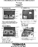
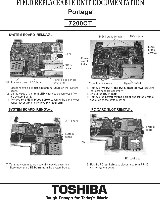
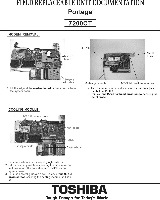
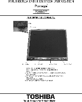
FIELD REPLACEABLE UNIT DOCUMENTATION Portege" 7200CT SYSTEM BOARD REMOVAL 2N One acre 0C-INjec J33 sows Iv12x4 Bess screw LED board P. lose sensor ler ,,L rrnect the Millie, cable from N. on the system 2 .the edge OMB front LED board to disconnect it from the system board. 3 Remove one IQ. brass screw securing the panel close sensor lever arm a. remove the lever arm SYSTEM BOARD REMOVAL SCIPWS System board 4.1,1,:rnwosrVirnvo,olfrdtazdmftx6 brass screws securing 5 out.. 0C Mck Slimmers the power switch holder and lift the system board out of the bottom cover PC CARD SLOT REMOVAL hgr:Irn PJ410 ' TdiusTotnhneenee=0:YfT0Z'gsdy:ttlnoZ PC card slot 8 Pull the PC card slots to disconnect from P.,110 on the system board TOSHIBA Tough Enough for Today's World.
-
 1
1 -
 2
2 -
 3
3 -
 4
4 -
 5
5 -
 6
6 -
 7
7 -
 8
8
 |
 |
