Toshiba RD-XS52 Owners Manual - Page 21
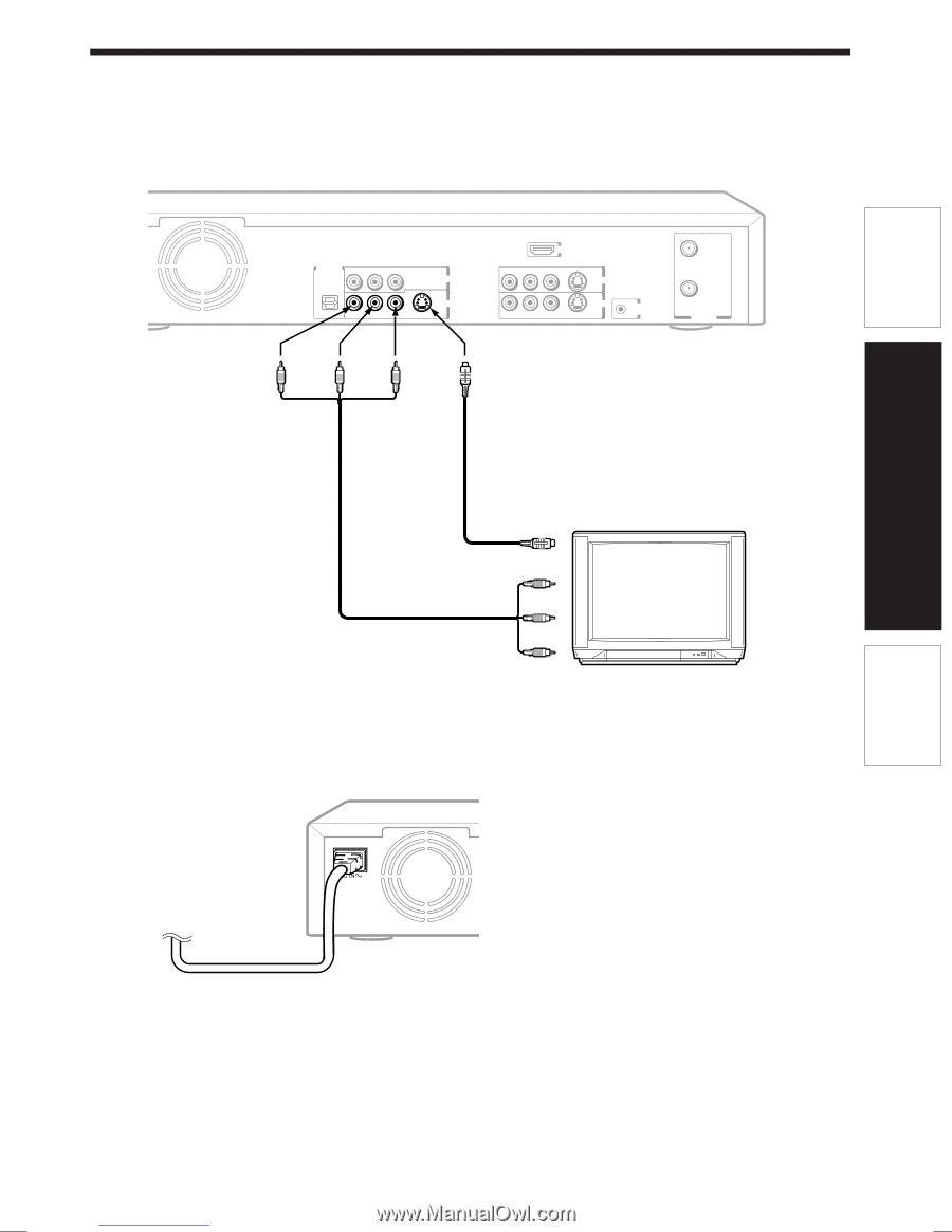
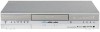
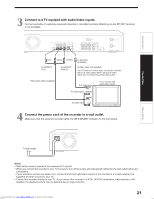
Connect to a TV equiped with audio/video inputs., Connect the power cord of the recorder to a wall
 |
View all Toshiba RD-XS52 manuals
Add to My Manuals
Save this manual to your list of manuals |
Page 21 highlights
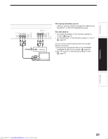
Introduction 3 Connect to a TV equiped with audio/video inputs. Connect as below for watching received channels or recorded contents. Watching via the RF OUT terminal is not available. DIGITAL AUDIO OUTPUT Y PB PR BITSTREAM/PCM COMPONENT OUTPUT OPTICAL R L VIDEO S-VIDEO OUTPUT HDMI OUTPUT R L VIDEO S-VIDEO INPUT1 INPUT3 CHANNEL R L VIDEO S-VIDEO CHANGE IR RF IN (FROM ANT.) RF OUT (TO TV) VHF / UHF (red) To OUTPUT (R/L) (white) (yellow) To OUTPUT (VIDEO) To OUTPUT (S-VIDEO) S-Video cable (not supplied) If the TV has an S-video input, connect the recorder with an S-video cable. When using an S-video cable, do not connect the yellow video cable. Video/audio cable (supplied) To S-video input TV or monitor with audio/video inputs To video inputs (yellow) (white) To audio input (red) 4 Connect the power cord of the recorder to a wall outlet. Make sure that the powered recorder lights the ON/STANDBY indicator on the front panel. Connections Basic Setup To wall outlet Notes • Refer to the owner's manual of the connected TV as well. • When you connect the recorder to your TV, be sure to turn off the power and unplug both units from the wall outlet before any connections. • If your television set has one audio input, connect the left and right audio outputs of the recorder to a Y cable adapter (not supplied) and then connect to your TV. • Connect the recorder directly to your TV. If you connect the recorder to a VCR, TV/VCR combination, video selector or AV amplifier, the playback picture may be distorted due to copy protection. Downloaded from www.Manualslib.com manuals search engine 21
-
 1
1 -
2
-
3
-
4
-
5
-
6
-
7
-
8
-
9
-
10
-
11
-
12
-
13
-
14
-
15
-
 16
16 -
 17
17 -
 18
18 -
 19
19 -
 20
20 -
 21
21 -
 22
22 -
 23
23 -
 24
24 -
 25
25 -
 26
26 -
27
-
28
-
29
-
30
-
31
-
32
-
33
-
34
-
35
-
36
-
37
-
38
-
39
-
40
-
41
-
42
-
43
-
44
-
45
-
46
-
47
-
48
-
49
-
50
-
51
-
52
-
53
-
54
-
55
-
56
-
57
-
58
-
59
-
60
 |
 |