Toshiba Satellite L755 User Manual - Page 62
Slide your fingernail or a thin object under the cover and lift it off. - battery replacement
 |
View all Toshiba Satellite L755 manuals
Add to My Manuals
Save this manual to your list of manuals |
Page 62 highlights
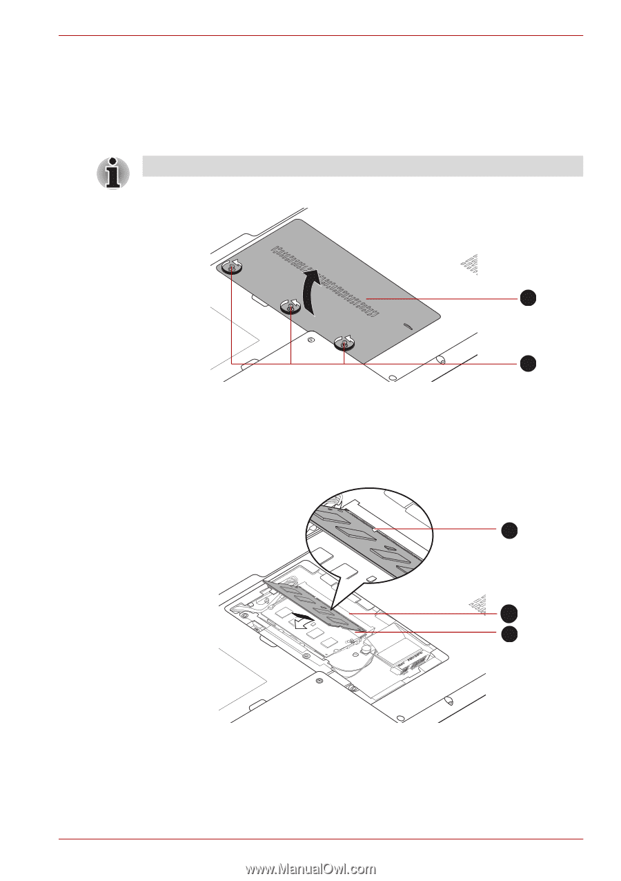
Hardware, Utilities and Options 4. Turn the computer upside down and remove the battery pack (refer to Replacing the battery pack section in Chapter 6, Power and Power-Up Modes, if required). 5. Loosen the screws securing the memory module cover in place - please note that this screw is attached to the cover in order to prevent it from being lost. Use a point size 0 Phillips screwdriver. 6. Slide your fingernail or a thin object under the cover and lift it off. 1 2 1. Memory module cover 2. Screws Removing the memory module cover 7. Align the notch of the memory module with that of the memory slot and gently insert the module into the slot at about a 45 degree angle before holding it down until the latches on either side snap into place. 1 2 3 1. Notch 2. Slot B User's Manual 3. Slot A Seating the memory module 3-18
-
 1
1 -
2
-
3
-
4
-
5
-
6
-
7
-
8
-
9
-
10
-
11
-
12
-
13
-
14
-
15
-
16
-
17
-
18
-
19
-
20
-
21
-
22
-
23
-
24
-
25
-
26
-
27
-
28
-
29
-
30
-
31
-
32
-
33
-
34
-
35
-
36
-
37
-
38
-
39
-
40
-
41
-
42
-
43
-
44
-
45
-
46
-
47
-
48
-
49
-
50
-
51
-
52
-
53
-
54
-
55
-
56
-
 57
57 -
 58
58 -
 59
59 -
 60
60 -
 61
61 -
 62
62 -
 63
63 -
 64
64 -
 65
65 -
 66
66 -
 67
67 -
68
-
69
-
70
-
71
-
72
-
73
-
74
-
75
-
76
-
77
-
78
-
79
-
80
-
81
-
82
-
83
-
84
-
85
-
86
-
87
-
88
-
89
-
90
-
91
-
92
-
93
-
94
-
95
-
96
-
97
-
98
-
99
-
100
-
101
-
102
-
103
-
104
-
105
-
106
-
107
-
108
-
109
-
110
-
111
-
112
-
113
-
114
-
115
-
116
-
117
-
118
-
119
-
120
-
121
-
122
-
123
-
124
-
125
-
126
-
127
-
128
-
129
-
130
-
131
-
132
-
133
-
134
-
135
-
136
-
137
-
138
-
139
-
140
-
141
-
142
-
143
-
144
-
145
-
146
-
147
-
148
-
149
-
150
-
151
-
152
-
153
-
154
-
155
-
156
-
157
-
158
-
159
-
160
-
161
-
162
-
163
-
164
-
165
-
166
-
167
-
168
-
169
-
170
-
171
-
172
-
173
-
174
-
175
-
176
-
177
-
178
-
179
 |
 |