Toshiba TLP-T401U LCD Projector TLP-T400/T500/T700 Users Guide (PDF) - Page 8
Checking the package contents, Names of each part on the main unit
 |
View all Toshiba TLP-T401U manuals
Add to My Manuals
Save this manual to your list of manuals |
Page 8 highlights
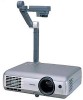
Checking the package contents Please make sure that the following items are included in the box, along with the main unit. If an item is missing, please contact the store from which you purchased the product immediately. (1) VOL.- PJ MODE STOP VOL.+ LASER MENUR/E-CNLTIECIRNKPUT PLAY (5) (9) (13) (2) (6) (10) (3) (7) (11) (14) (4) (8) (12) I (1) Remote control I (2) AAA dry-cell batteries for remote control (2) I (3) Wireless LAN PC card (See note 1) I (3) Information to the user (See note 1) I (4) Quick Reference I (5) CD-ROM I (6) Owner's Manual (this document) I (7) Power cord (See note 3) I (8) RGB cable I (9) AV cable I (10) Audio cable (for computer) I (11) USB cable (See note 2) I (12) Mouse remote control receiver (See note 1) I (13) Carrying bag I (14) License information (See note 1) Notes 1: Included with models equipped with PC card slot. 2: Included with models not equipped with PC card slot. 3: The shape and number of power cords supplied vary depending on the product destination. NThe Supplied CD-ROM The supplied CD-ROM contains an owner's manual including information omitted in the Owner's manual (Getting started), Acrobat® Reader™, which is needed to view the manual, and applications p.24 for using the functions of models equipped with a PC card slot. I Installing Acrobat® Reader™ Windows: In the CD-ROM, select the Reader/English folder, and run ar500enu.exe. Follow the on-screen instructions. Macintosh: In the CD-ROM, select the Reader/English folder, and run Reader Installer. Follow the on-screen instructions to install the software. I Viewing the manual In the CD-ROM, double-click on Start.pdf. Acrobat® Reader™ launches, and the menu screen of the Owner's manual appears. Click on your language. The Owner's Manual cover and list of bookmarks appear. Click on a bookmark title to view that section of the manual. Click on p. to view a reference page with related information. See the Help menu for more information about Acrobat® Reader™. 14 Names of each part on the main unit (6) (5) (4) (3) (2) (1) (17) (7) (8) (15) (14) (9) (10) (11) (12) (13) INPUT ON/STANDBY KAEUYTSOTONE AUTO SET VOL.- MENU VOL.+ FAN TEMP LAMP ON (19) (18)(22) (20) (15) (14) LED Light (21) (13) INPUT AKUEYTSOTONE ON/STANDBY MENU VOL.+ AUTO SET VOL.- FAN TEMP LAMP ON LOCKW.BSATLOIAMRNAECGEE OVERLAY ARM LIGHT CAMEGRAAIN CAMERA (14) (10) (16) (1) (15) (14) (10) (16) (15)(1) Name : Function (1) Infrared remote sensor : Senses commands from the remote control p.19 (2) Lens : Projects expanded image (3) Zooming lever : Adjusts screen size p.28 (4) Focusing ring : Adjusts screen focus p.28 (5) Air exhaust : Expels air that has grown hot inside the projector (6) Speaker : Plays audio (7) AC IN socket : Connect the supplied power cord here p.25 (8) Anti-theft lock hole : Attach a security chain, etc. here (9) Lamp cover : Remove to replace lamp p.58 (10) Tilt adjuster : Adjusts the projector's horizontal tilt p.28 (11) Foot adjuster : Adjusts the vertical projection angle p.28 (12) Foot adjuster release button : Press to stow the foot adjuster p.28 (13) Control panel : Operates the projector p.16 (14) Connection terminal cover : Remove to connect to an external device p.18 (15) Air intake : Draws in air from outside unit (16) PC card slot cover [See note 1] : Remove to mount/remove the PC card p.23 (17) Camera head [See note 2] : The document camera (18) Camera lens [See note 2] : The document camera's lens (19) Camera focusing ring [See note 2] : Adjusts document camera focus p.45 (20) Camera arm [See note 2] : Adjusts the camera angle p.44 (21) Camera control panel [See note 2] : Operates the document camera p.17 (22) Camera light [See note 2] : Shines light on the object that the document camera is photographing p.44 Notes 1: Models equipped with PC card slot 2: Models equipped with document camera 15 Preparations
-
 1
1 -
2
-
 3
3 -
 4
4 -
 5
5 -
 6
6 -
 7
7 -
 8
8 -
 9
9 -
 10
10 -
 11
11 -
 12
12 -
 13
13 -
14
-
15
-
16
-
17
-
18
-
19
-
20
-
21
-
22
-
23
-
24
-
25
-
26
-
27
-
28
-
29
-
30
-
31
-
32
-
33
-
34
-
35
-
36
 |
 |
